|
1
|
RECORD VEHICLE STATUS WHEN DTC WAS DETECTED TO UTILIZE WITH REPEATABILITY VERIFICATION
-
Note
-
• Recording can be facilitated using the screen capture function of the PC.
• Record the freeze frame data/snap shot data.
|
—
|
Go to the next step.
|
|
2
|
INSPECT A/F SENSOR CONNECTOR CONNECTION
• Switch the ignition OFF.
• Disconnect the A/F sensor connector.
• Inspect the connector engagement and connection condition, and inspect the terminals for damage, deformation, corrosion, or disconnection.
• Is the connector normal?
|
Yes
|
Go to the next step.
|
|
No
|
Repair or replace the connector, then go to Step 8.
|
|
3
|
INSPECT A/F SENSOR HEATER
• Inspect the A/F sensor heater.
• Is the A/F sensor heater normal?
|
Yes
|
Go to the next step.
|
|
No
|
Replace the A/F sensor, then go to Step 8.
|
|
4
|
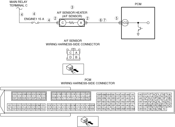
INSPECT A/F SENSOR HEATER POWER SUPPLY CIRCUIT FOR OPEN CIRCUIT OR SHORT TO GROUND
• Verify that the A/F sensor connector is disconnected.
• Switch the ignition ON (engine off).
-
Note
-
• Another DTC may be stored by the PCM detecting an open circuit.
• Measure the voltage at A/F sensor terminal C (vehicle wiring harness side).
• Is the voltage B+?
|
Yes
|
Go to the next step.
|
|
No
|
Inspect the ENGINE1 15 A fuse.
If the fuse is blown:
• Refer to the wiring diagram and verify if there is a common connector between main relay terminal C and A/F sensor terminal C.
If there is a common connector:
-
― Inspect the common connector and terminals for corrosion, damage, or disconnection and the common wiring harnesses for short to ground to determine the malfunctioning location.
― Repair or replace the malfunctioning location.
If there is no common connector:
-
― Repair or replace the wiring harness which is shorted to ground.
― Replace the fuse.
If the fuse is damaged:
• Replace the fuse.
If the fuse is normal:
• Refer to the wiring diagram and verify if there is a common connector between main relay terminal C and A/F sensor terminal C.
If there is a common connector:
-
― Inspect the common connector and terminals for corrosion, damage, or disconnection and the common wiring harnesses for an open circuit to determine the malfunctioning location.
― Repair or replace the malfunctioning location.
If there is no common connector:
-
― Repair or replace the wiring harness which has an open circuit.
Go to Step 8.
|
|
5
|
INSPECT PCM CONNECTOR CONDITION
• Disconnect the PCM connector.
• Inspect the connector engagement and connection condition, and inspect the terminals for damage, deformation, corrosion, or disconnection.
• Is the connector normal?
|
Yes
|
Go to the next step.
|
|
No
|
Repair or replace the connector, then go to Step 8.
|
|
6
|
INSPECT A/F SENSOR HEATER CONTROL CIRCUIT FOR SHORT TO GROUND
• Verify that the A/F sensor connector and the PCM connector are disconnected.
• Switch the ignition OFF.
• Inspect for continuity between A/F sensor terminal A (vehicle wiring harness side) and body ground.
• Is there continuity?
|
Yes
|
Refer to the wiring diagram and verify if there is a common connector between A/F sensor terminal A and PCM terminal 1CG.
If there is a common connector:
• Inspect the common connector and terminals for corrosion, damage, or disconnection and the common wiring harnesses for short to ground to determine the malfunctioning location.
• Repair or replace the malfunctioning location.
If there is no common connector:
• Repair or replace the wiring harness which is shorted to ground.
Go to Step 8.
|
|
No
|
Go to the next step.
|
|
7
|
INSPECT A/F SENSOR HEATER CONTROL CIRCUIT FOR OPEN CIRCUIT
• Verify that the A/F sensor connector and the PCM connector are disconnected.
• Switch the ignition OFF.
• Inspect the wiring harness for continuity between A/F sensor terminal A (vehicle wiring harness side) and PCM terminal 1CG (vehicle wiring harness side).
• Is there continuity?
|
Yes
|
Go to the next step.
|
|
No
|
Refer to the wiring diagram and verify if there is a common connector between A/F sensor terminal A and PCM terminal 1CG.
If there is a common connector:
• Inspect the common connector and terminals for corrosion, damage, or disconnection and the common wiring harnesses for an open circuit to determine the malfunctioning location.
• Repair or replace the malfunctioning location.
If there is no common connector:
• Repair or replace the wiring harness which has an open circuit.
Go to the next step.
|
|
8
|
VERIFY THAT REPAIRS HAVE BEEN COMPLETED
• Reconnect all the disconnected connectors.
• Refer to the [MEMORY CLEARING PROCEDURE] and clear the DTC.
• Start the engine and warm it up.
• Stop all electrical loads. (Such as A/C, headlights, blower fan, rear window defroster)
• Drive the vehicle on flat roads under the following conditions 5 times repeatedly.
-
1. After the engine is started, idle the engine for 30 s.
2. Accelerate in 2nd gear to 35 km/h and drive the vehicle while maintaining the speed for 25 s.
3. Stop the vehicle, switch the ignition OFF, and wait for 20 s.
4. Accelerate in 3rd gear to 50 km/h and drive the vehicle while maintaining the speed for 50 s.
5. Stop the vehicle and idle the engine for 20 s.
• Stop the engine.
• Display the DTCs using the M-MDS.
• Has DTC P0031:00 been recorded?
|
Yes
|
Repeat the inspection from Step 1.
• If the malfunction recurs, replace the PCM, then go to the next step.
|
|
No
|
Go to the next step.
|
|
9
|
VERIFY OTHER DTCs
• Has any other DTC or pending code been stored?
|
Yes
|
Repair the malfunctioning location according to the applicable DTC troubleshooting.
|
|
No
|
DTC troubleshooting completed.
|