 |
ac8wzw00002914
DTC P0421:00 [PCM (SKYACTIV-D 2.2)]
id0102j5704400
Details On DTCs
|
DESCRIPTION |
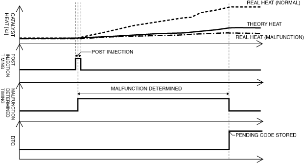
Catalyst efficiency below threshold |
|
|---|---|---|
|
DETECTION CONDITION
|
Determination conditions
|
• The PCM determines that the actual heat amount of the exhaust gas is lower than the estimated heat amount under the vehicle conditions after post injection is completed during diesel particulate filter regeneration control.
|
|
DETECTION CONDITION
|
Preconditions
|
• If any of the following conditions is met under condition A, condition B and condition C:
Condition A:
Condition B: the following conditions continue for 3 s or more
Condition C:
|
|
Drive cycle
|
• 2
|
|
|
Self test type
|
• CMDTC self test
|
|
|
Sensor used
|
• Exhaust gas temperature sensor No.2
• Exhaust gas temperature sensor No.3
|
|
|
FAIL-SAFE FUNCTION
|
• Not applicable
|
|
|
VEHICLE STATUS WHEN DTCs ARE OUTPUT
|
• Check engine light is illuminated
|
|
|
POSSIBLE CAUSE
|
• Erratic signal to PCM
• Exhaust gas leakage from exhaust system
• Exhaust gas temperature sensor No.2 malfunction
• Exhaust gas temperature sensor No.3 malfunction
• Improper operation of fuel injector
• Catalytic converter or diesel particulate filter malfunction (deformation, damage)
• PCM malfunction
|
|
System Wiring Diagram
Function Explanation (DTC Detection Outline)
ac8wzw00002914
|
Repeatability Verification Procedure
PID Item/Simulation Item Used In Diagnosis
PID/DATA monitor item table
|
Item |
Definition |
Unit |
Condition/Specification |
|---|---|---|---|
|
EXHTEMP2
|
Exhaust temperature sensor No.2
|
°C, °F
|
• Displays the exhaust gas temperature before passing catalytic converter
|
|
EXHTEMP3
|
Exhaust temperature sensor No.3
|
°C, °F
|
• Displays the exhaust gas temperature after passing catalytic converter
|
Function Inspection Using M-MDS
|
STEP |
INSPECTION |
ACTION |
|
|---|---|---|---|
|
1
|
PURPOSE: VERIFY RELATED SERVICE INFORMATION AVAILABILITY
• Verify related Service Information availability.
• Is any related Service Information available?
|
Yes
|
Perform repair or diagnosis according to the available Service Information.
• If the vehicle is not repaired, go to the next step.
|
|
No
|
Go to the next step.
|
||
|
2
|
PURPOSE: IDENTIFY TRIGGER DTC FOR FREEZE FRAME DATA
• Is the DTC P0421:00 on FREEZE FRAME DATA?
|
Yes
|
Go to the next step.
|
|
No
|
Go to the troubleshooting procedure for DTC on FREEZE FRAME DATA.
|
||
|
3
|
PURPOSE: RECORD VEHICLE STATUS AT TIME OF DTC DETECTION TO UTILIZE WITH REPEATABILITY VERIFICATION
• Record the FREEZE FRAME DATA/snapshot data on the repair order.
|
—
|
Go to the next step.
|
|
4
|
PURPOSE: VERIFY IF DIAGNOSTIC RESULT IS AFFECTED BY OTHER RELATED DTCs OCCURRING
• Switch the ignition off, then ON (engine off).
• Perform the Pending Trouble Code Access Procedure and DTC Reading Procedure.
• Is the other PENDING CODE/DTC also present?
|
Yes
|
Go to the applicable DTC inspection.
|
|
No
|
Go to the next step.
|
||
|
5
|
PURPOSE: VERIFY IF THERE IS PID ITEM CAUSING DRASTIC CHANGES OF ACCELERATION FLUCTUATION BY INPUT SIGNAL TO PCM AND DSC HU/CM
• Access the following PIDs using the M-MDS:
• Is there any signal that is far out of specification?
|
Yes
|
Go to the next step.
|
|
No
|
Go to the troubleshooting procedure to perform the procedure from Step 1.
|
||
|
6
|
PURPOSE: VERIFY CONNECTOR CONNECTIONS
• Access the following PIDs using the M-MDS:
• When the following parts are shaken, does the PID value include a PID item which has changed?
|
Yes
|
Inspect the related wiring harness and connector.
• Repair or replace the malfunctioning part.
Go to the next step.
|
|
No
|
Go to the troubleshooting procedure to perform the procedure from Step 1.
|
||
|
7
|
PURPOSE: VERIFY DIFFERENCE IN TEMPERATURE BEFORE AND AFTER PASSING CATALYTIC CONVERTER DURING COMPULSORY DIESEL PARTICULATE FILTER REGENERATION AND VERIFY IF CATALYTIC CONVERTER IS OPERATING NORMALLY AGAIN
• Access the following PIDs using the M-MDS:
• Perform the "COMPULSORY DIESEL PARTICULATE FILTER REGENERATION".
• Is the difference in values between PID EXHTEMP2 and EXHTEMP3 50 °C {122 °F} or more after approx. 3 min from the implementation start time of compulsory diesel particulate filter regeneration?
|
Yes
|
Go to the troubleshooting procedure to perform the procedure from Step 1.
|
|
No
|
Malfunction in the catalytic converter or the diesel particulate filter in the catalytic converter can be considered.
Replace the catalytic converter, then go to the next step.
|
||
|
8
|
PURPOSE: VERIFY DIFFERENCE IN TEMPERATURE BEFORE AND AFTER PASSING CATALYTIC CONVERTER DURING COMPULSORY DIESEL PARTICULATE FILTER REGENERATION AND VERIFY IF CATALYTIC CONVERTER IS OPERATING NORMALLY
• Access the following PIDs using the M-MDS:
• Perform the "COMPULSORY DIESEL PARTICULATE FILTER REGENERATION".
• Is the difference in values between PID EXHTEMP2 and EXHTEMP3 50 °C {122 °F} or more after approx. 3 min from the implementation start time of compulsory diesel particulate filter regeneration?
|
Yes
|
Go to the troubleshooting procedure to perform the procedure from Step 1.
|
|
No
|
Go to the troubleshooting procedure to perform the procedure from Step 6.
|
||
Troubleshooting Diagnostic Procedure
Function Inspection Using M-MDS
|
STEP |
INSPECTION |
ACTION |
|
|---|---|---|---|
|
1
|
PURPOSE: INSPECT EXHAUST SYSTEM FOR LEAKAGE
• Visually inspect for exhaust gas leakage from the exhaust system.
• Is there any malfunction?
|
Yes
|
Repair or replace the malfunctioning part according to the inspection results, then go to Step 5.
|
|
No
|
Go to the next step.
|
||
|
2
|
PURPOSE: INSPECT EXHAUST GAS TEMPERATURE SENSOR NO.2
• Inspect the exhaust gas temperature sensor No.2.
• Is there any malfunction?
|
Yes
|
Replace the exhaust gas temperature sensor No.2, then go to Step 5.
|
|
No
|
Go to the next step.
|
||
|
3
|
PURPOSE: INSPECT EXHAUST GAS TEMPERATURE SENSOR NO.3
• Inspect the exhaust gas temperature sensor No.3.
• Is there any malfunction?
|
Yes
|
Replace the exhaust gas temperature sensor No.3, then go to Step 5.
|
|
No
|
Go to the next step.
|
||
|
4
|
PURPOSE: INSPECT FOR MALFUNCTION FUEL INJECTOR
• Inspect the fuel injector.
• Is there any malfunction?
|
Yes
|
Replace the suspect fuel injector, then go to the next step.
|
|
No
|
Catalytic converter or diesel particulate filter can be considered the cause.
• Replace the catalytic converter, then go to the next step.
|
||
|
5
|
PURPOSE: VERIFY IF PCM SOFTWARE VERSION IS UP TO DATE
• Always reconnect all disconnected connectors.
• Clear the DTC from the PCM memory using the M-MDS.
• Verify if the PCM software version is up to date.
• Is the PCM software version up to date?
|
Yes
|
Go to the next step.
|
|
No
|
Reprogram the PCM software version to the latest, then go to the next step.
|
||
|
6
|
PURPOSE: PERFORM DTC INSPECTION AND VERIFY IF MALFUNCTIONING PART IS PCM
• Always reconnect all disconnected connectors.
• Clear the DTC from the PCM memory using the M-MDS.
• Implement the repeatability verification procedure.
• Perform the Pending Trouble Code Access Procedure.
• Is the PENDING CODE for this DTC present?
|
Yes
|
Repeat the inspection from Step 1.
• If the malfunction recurs, replace the PCM.
Go to the next step.
|
|
No
|
Go to the next step.
|
||
|
7
|
PURPOSE: VERIFY AFTER REPAIR PROCEDURE
• Perform the “AFTER REPAIR PROCEDURE”.
• Are any DTCs present?
|
Yes
|
Go to the applicable DTC inspection.
|
|
No
|
DTC troubleshooting completed.
|
||