DTC P21CE:00 [PCM (SKYACTIV-D 2.2)]


id0102j5725400

DTC P21CE:00

Reductant quality module performance

DETECTION CONDITION
•  The PCM detects any of the following for a continuous 5 s.
―  Urea quality sensor power supply voltage: Less than 4.33 V
―  Any of the following is detected for 0.5 s or more
•  Analog/digital conversion processing time: 500 msec or more
•  Error in analog/digital conversion results
―  The following comparison results do not match
•  Check sum data calculated when AdBlue® quality sensor is starting
•  Check sum data stored in urea quality sensor
―  The following comparison results do not match
•  Sensor characteristics calculated when urea quality sensor is starting
•  Sensor characteristics stored in urea quality sensor
―  Heater voltage in urea quality sensor is less than 0.2 V or exceeds 4.8 V when heater is on
―  Heater voltage in urea quality sensor is less than 0.02 V or exceeds 0.2 V when heater is off
―  Input current is less than 0.02 A or exceeds 0.1 A when heater in urea quality sensor turns on
―  Communication error between CPU and digital potentiometer in urea quality sensor
MONITORING CONDITIONS
•  AdBlue® amount in the urea tank: 61—400 mm {2.5—15.7 in}
•  Above 9 s have elapsed after the ignition was switched ON
•  The following DTCs are not detected
―  Urea quality sensor: U02A2:00
Diagnostic support note
•  This is a continuous monitor (other).
•  The check engine light illuminates if the PCM detects the above malfunction condition during the first drive cycle.
•  FREEZE FRAME DATA/Snapshot data is available.
•  DTC is stored in the PCM memory.
Note
•  When this DTC is detected, inducement DTC P2BAF:00 is also detected
FAIL-SAFE FUNCTION
•  The instrument cluster warns the driver with the following functions.
―  Selective catalytic reduction (SCR) system warning light
―  Buzzer
―  Message
Note
•  The remaining distance to empty is a maximum of 700 km {435 mile} until the malfunction targeted by inducement (laws and regulations requirement) is repaired. This distance is displayed in the instrument cluster and counts down until the targeted malfunction is repaired.
•  Perform the following restrictions while driving the vehicle according to the remaining distance to empty.
―  700 to 650 km {435 to 404 miles}: No restriction
―  650 to 0 km {404 to 0 miles}: Maximum vehicle speed is restricted from 80 to 50 km/h {50 to 31 mph}
―  0 km {0 miles}: Engine speed is fixed at idle speed
POSSIBLE CAUSE
•  Dosing control unit malfunction
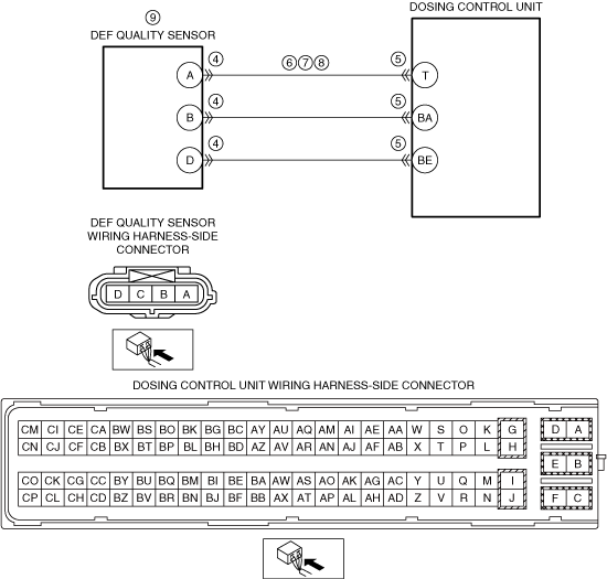
•  Urea quality sensor connector or terminals malfunction
•  Dosing control unit connector or terminals malfunction
•  Open or short circuit in wiring harness between urea quality sensor terminal A and dosing control unit terminal T
•  Urea quality sensor malfunction
―  Power supply circuit in urea quality sensor
―  CPU in urea quality sensor
―  Heater in urea quality sensor
•  Dosing control unit malfunction
•  PCM malfunction

Diagnostic Procedure

STEP

INSPECTION

ACTION

1
RECORD VEHICLE STATUS AT TIME OF DTC DETECTION TO UTILIZE WITH REPEATABILITY VERIFICATION
Note
•  Recording can be facilitated using the screen capture function of the PC.
•  Record the FREEZE FRAME DATA/snapshot data on the repair order.
Go to the next step.
2
VERIFY RELATED SERVICE INFORMATION AVAILABILITY
•  Verify related Service Bulletins and/or on-line repair information availability.
•  Is any related Service Information available?
Yes
Perform repair or diagnosis according to the available repair information.
•  If the vehicle is not repaired, go to the next step.
No
Go to the next step.
3
VERIFY DOSING CONTROL UNIT RELATED DTC
•  Retrieve dosing control unit DTCs using the M-MDS.
•  Are any DTCs present?
Yes
Go to the applicable DTC inspection.
No
Go to the next step.
4
INSPECT UREA QUALITY SENSOR CONNECTOR CONDITION
•  Switch the ignition off.
•  Disconnect the urea quality sensor connector.
•  Inspect for poor connection (such as damaged/pulled-out pins, corrosion).
•  Is there any malfunction?
Yes
Repair or replace the connector and/or terminals, then go to Step 11.
No
Go to the next step.
5
INSPECT DOSING CONTROL UNIT CONNECTOR CONDITION
•  Disconnect the dosing control unit connector.
•  Inspect for poor connection (such as damaged/pulled-out pins, corrosion).
•  Is there any malfunction?
Yes
Repair or replace the connector and/or terminals, then go to Step 11.
No
Go to the next step.
6
INSPECT UREA QUALITY SENSOR CIRCUIT FOR OPEN CIRCUIT
•  Verify that the urea quality sensor and dosing control unit connectors are disconnected.
•  Inspect for continuity between the following terminals (wiring harness-side):
―  Urea quality sensor terminal A—Dosing control unit terminal T
•  Is there continuity?
Yes
Go to the next step.
No
•  Refer to the wiring diagram and verify whether or not there is a common connector between the following terminals:
―  Urea quality sensor terminal A—Dosing control unit terminal T
If there is a common connector:
•  Determine the malfunctioning part by inspecting the common connector and the terminal for corrosion, damage, or pin disconnection, and the common wiring harness for an open circuit.
•  Repair or replace the malfunctioning part.
If there is no common connector:
•  Repair or replace the wiring harness which has an open circuit.
Go to Step 11.
7
INSPECT UREA QUALITY SENSOR CIRCUIT FOR SHORT TO POWER SUPPLY
•  Verify that the urea quality sensor and dosing control unit connectors are disconnected.
•  Switch the ignition ON (engine off).
Note
•  Another DTC may be stored by the dosing control unit detecting an open circuit.
•  Measure the voltage at the following terminals (wiring harness-side):
―  Urea quality sensor terminal A
•  Is the voltage 0 V?
Yes
Go to the next step.
No
•  Refer to the wiring diagram and verify whether or not there is a common connector between the following terminals:
―  Urea quality sensor terminal A—Dosing control unit terminal T
If there is a common connector:
•  Determine the malfunctioning part by inspecting the common connector and the terminal for corrosion, damage, or pin disconnection, and the common wiring harness for a short to power supply.
•  Repair or replace the malfunctioning part.
If there is no common connector:
•  Repair or replace the wiring harness which has a short to power supply.
Go to Step 11.
8
INSPECT UREA QUALITY SENSOR CIRCUIT FOR SHORT TO GROUND
•  Verify that the urea quality sensor and dosing control unit connectors are disconnected.
•  Inspect for continuity between the following terminals (wiring harness-side) and body ground:
―  Urea quality sensor terminal A
•  Is there continuity?
Yes
•  Refer to the wiring diagram and verify whether or not there is a common connector between the following terminals:
―  Urea quality sensor terminal A—Dosing control unit terminal T
If there is a common connector:
•  Determine the malfunctioning part by inspecting the common connector and the terminal for corrosion, damage, or pin disconnection, and the common wiring harness for a short to ground.
•  Repair or replace the malfunctioning part.
If there is no common connector:
•  Repair or replace the wiring harness which has a short to ground.
Go to Step 11.
No
Go to the next step.
9
INSPECT UREA QUALITY SENSOR
•  Inspect the urea quality sensor.
•  Is there any malfunction?
Yes
Replace the urea quality sensor, then go to Step 11.
No
Go to the next step.
10
INSPECT PCM CONNECTOR CONDITION
•  Disconnect the PCM connector.
•  Inspect for poor connection (such as damaged/pulled-out pins, corrosion).
•  Is there any malfunction?
Yes
Repair or replace the connector and/or terminals, then go to the next step.
No
Go to the next step.
11
VERIFY DTC TROUBLESHOOTING COMPLETED
•  Always reconnect all disconnected connectors.
•  Clear the DTC from the PCM memory using the M-MDS.
•  Switch the ignition ON (engine off) and leave for 1 min.
•  Start the engine and wait for 1 min.
•  Display the DTCs using the M-MDS.
•  Has DTC P21CE:00 been recorded?
Yes
Repeat the inspection from Step 1.
•  If the malfunction recurs, replace the PCM.
Go to the next step.
No
Go to the next step.
12
VERIFY AFTER REPAIR PROCEDURE
•  Perform the “AFTER REPAIR PROCEDURE”.
•  Are any DTCs present?
Yes
Go to the applicable DTC inspection.
No
DTC troubleshooting completed.