DTC P202E:00 [DOSING CONTROL UNIT (SKYACTIV-D 2.2)]


id0102k1721200

DTC P202E:00

Urea injector circuit range/performance problem

DETECTION CONDITION
•  If any of the following conditions is met under condition A or condition B: 2 s in the control circuit of the urea injector.
Condition A:
•  A condition in which the urea injector current is low or the inductance of the urea injector is low exceeds 40 times even though the dosing control unit energizes the urea injector during AdBlue® injection control or AdBlue® defroster control.
MONITORING CONDITIONS
―  Ignition switched ON (engine off or on)
―  SCR control is operating
―  Battery voltage: 10.9—16 V
―  Urea injector heater control is operating
―  The following conditions are met:
•  UREA injector: P2047:00, P2048:00, P2049:00
Diagnostic support note
―  This is an intermittent monitor (CCM).
―  The check engine light illuminates if the PCM detects the above malfunction condition during the first drive cycle.
―  FREEZE FRAME DATA / Snapshot data is available.
―  DTC is stored in the dosing control unit memory.
Condition B:
•  When the following condition is met, the NOx sensor No.1 detects the urea injector coil temperature than more 33.5 °C {92.3 °F} for 0.1 s:
MONITORING CONDITIONS
•  Less than 8 s after ignition is switched ON (engine off)
•  Battery voltage: 10.9—16 V
•  Ambient air temperature: -10.04 °C {13.93 °F} or more
•  Before starting the engine, leave the vehicle with the engine turned off for 6 hours or more.
•  Difference between maximum and minimum value of ambient temperature: 15 °C {59 °F} or less
•  Difference between maximum and minimum value of exhaust gas temperature sensor No.5: 15 °C {59 °F} or less
•  Difference between maximum and minimum value of ECT sensor No.1: 15 °C {59 °F} or less
•  The following conditions are met:
―  UREA injector: P2047:00, P2048:00, P2049:00
Note
•  P0615:00 may be stored if the remaining distance to empty is 0 km {0 mile} and the engine cannot be restarted.
•  DTC P1640:00 is also stored in the PCM.
Diagnostic support note
•  This is an intermittent monitor (CCM).
•  The check engine light illuminates if the dosing control unit detects the above malfunction condition in two consecutive drive cycles or in one drive cycle while the DTC for same malfunction has been stored in the dosing control unit.
•  PENDING CODE is available if the dosing control unit detects the above malfunction condition first driving cycle.
•  FREEZE FRAME DATA / Snapshot data is available.
•  DTC is stored in the dosing control unit memory.
FAIL-SAFE FUNCTION
•  Restricts the maximum remaining distance to empty.
•  Limits the upper limit of the engine speed.
POSSIBLE CAUSE
•  Urea injector connector or terminals malfunction
•  Dosing control unit connector or terminals malfunction
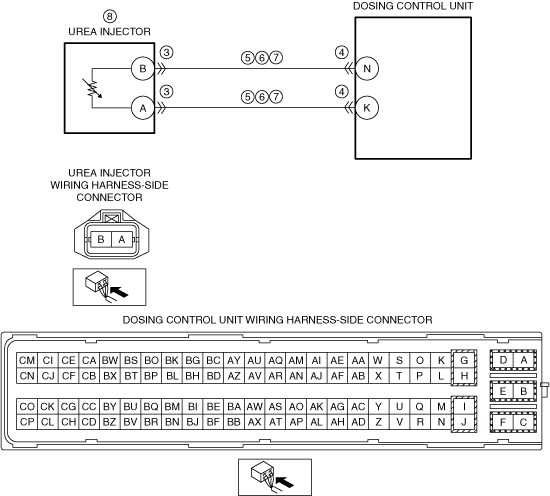
•  Short to ground in wiring harness between the following terminals:
―  Urea injector terminal B—dosing control unit terminal N
―  Urea injector terminal A—dosing control unit terminal K
•  Open circuit in wiring harness between the following terminals:
―  Urea injector terminal B—dosing control unit terminal N
―  Urea injector terminal A—dosing control unit terminal K
•  Urea injector malfunction
•  Dosing control unit malfunction

Diagnostic Procedure

STEP

INSPECTION

RESULTS

ACTION

1
RECORD VEHICLE STATUS AT TIME OF DTC DETECTION TO UTILIZE WITH REPEATABILITY VERIFICATION
Note
•  Recording can be facilitated using the screen capture function of the PC.
•  Record the snapshot data on the repair order.
Go to the next step.
2
VERIFY RELATED REPAIR INFORMATION AVAILABILITY
•  Verify related Service Information availability.
•  Is any related Service Information available?
Yes
Perform repair or diagnosis according to the available Service Information.
•  If the vehicle is not repaired, go to the next step.
No
Go to the next step.
3
INSPECT UREA INJECTOR CONNECTOR CONDITION
•  Switch the ignition off.
•  Disconnect the urea injector connector.
•  Inspect for poor connection (such as damaged/pulled-out pins, corrosion).
•  Is there any malfunction?
Yes
Repair or replace the connector and/or terminals, then go to Step 8.
No
Go to the next step.
4
INSPECT DOSING CONTROL UNIT CONNECTOR CONDITION
•  Disconnect the dosing control unit connector.
•  Inspect for poor connection (such as damaged/pulled-out pins, corrosion).
•  Is there any malfunction?
Yes
Repair or replace the connector and/or terminals, then go to Step 8.
No
Go to the next step.
5
INSPECT UREA INJECTOR CIRCUIT FOR SHORT TO GROUND
•  Verify that the urea injector and dosing control unit connectors are disconnected.
•  Inspect for continuity between the following terminals (wiring harness-side) and body ground:
―  Urea injector terminal B
―  Urea injector terminal A
•  Is there continuity?
Yes
Refer to the wiring diagram and verify whether or not there is a common connector between the following terminals:
•  Urea injector terminal B—dosing control unit terminal N
•  Urea injector terminal A—dosing control unit terminal K
If there is a common connector:
•  Determine the malfunctioning part by inspecting the common connector and the terminal for corrosion, damage, or pin disconnection, and the common wiring harness for a short to ground.
•  Repair or replace the malfunctioning part.
If there is no common connector:
•  Repair or replace the wiring harness which has a short to ground.
Go to Step 8.
No
Go to the next step.
6
INSPECT UREA INJECTOR CIRCUIT FOR OPEN CIRCUIT
•  Verify that the urea injector and dosing control unit connectors are disconnected.
•  Inspect for continuity between the following terminals (wiring harness-side):
―  Urea injector terminal B—dosing control unit terminal N
―  Urea injector terminal A—dosing control unit terminal K
•  Is there continuity?
Yes
Go to the next step.
No
Refer to the wiring diagram and verify whether or not there is a common connector between the following terminals:
•  Urea injector terminal B—dosing control unit terminal N
•  Urea injector terminal A—dosing control unit terminal K
If there is a common connector:
•  Determine the malfunctioning part by inspecting the common connector and the terminal for corrosion, damage, or pin disconnection, and the common wiring harness for an open circuit.
•  Repair or replace the malfunctioning part.
If there is no common connector:
•  Repair or replace the wiring harness which has an open circuit.
Go to Step 8.
7
INSPECT UREA INJECTOR
•  Inspect the urea injector.
•  Is there any malfunction?
Yes
Replace the urea injector, then go to the next step.
No
Go to the next step.
8
VERIFY THAT ENGINE CAN BE STARTED
•  Always reconnect all disconnected connectors.
•  Clear the DTC from the dosing control unit memory using the M-MDS.
Note
•  The engine cannot be restarted when the remaining distance to empty is 0 km {0 mile}.
•  Start the engine.
•  Can the engine be started?
Yes
Go to the next step.
No
Perform the “SCR INDUCEMENT INSPECTION SERVICE FUNCTION” using the M-MDS.
Note
•  When restriction of the remaining distance to empty is canceled, the SCR system warning light/SCR system warning indication turns off.
Go to the next step.
9
IMPLEMENT THE REPEATABILITY VERIFICATION PROCEDURE
•  Always reconnect all disconnected connectors.
•  Leave the vehicle for 6 h.
•  Leave for 20 s while idling.
•  Perform the “COMPULSORY DIESEL PARTICULATE FILTER REGENERATION”.
•  Perform acceleration/deceleration for 15 min repeatedly at a vehicle speed of 120 km/h {74.6 mph} or less.
•  Has the restriction of the remaining distance to empty been canceled?
Yes
Go to the next step.
No
Repeat the inspection from Step 8.
10
VERIFY DTC TROUBLESHOOTING COMPLETED
•  Retrieve the dosing control unit DTCs using the M-MDS.
•  Is the same Pending DTC present?
Yes
Go to the next step.
No
Repeat the inspection from Step 1.
•  If the malfunction recurs, replace the dosing control unit.
Go to the next step.
11
VERIFY IF OTHER DTCs DISPLAYED
•  Are any other DTCs displayed?
Yes
Repair or replace the malfunctioning part according to the applicable DTC troubleshooting.
No
DTC troubleshooting completed.