 |
ac5uuw00009783
DTC P220B:00 [DOSING CONTROL UNIT (SKYACTIV-D 2.2)]
id0102k1726300
Details On DTCs
|
DESCRIPTION |
NOx sensor No.2: power supply voltage malfunction |
|
|---|---|---|
|
DETECTION CONDITION
|
Determination conditions
|
• The NOx sensor No.2 internal supply voltage is not within the specified value for a continuous 30 s.
|
|
Preconditions
|
• Battery voltage: 10.9—16 V
• CAN communication is normal at engine start for a continuous 20 s or more
• The following DTCs is not detected:
|
|
|
Drive cycle
|
• 1
|
|
|
Self test type
|
• CMDTC self test
|
|
|
Sensor used
|
• NOx sensor No.2
• Dosing control unit
|
|
|
FAIL-SAFE FUNCTION
|
• Not applicable
|
|
|
VEHICLE STATUS WHEN DTCs ARE OUTPUT
|
• DTC P1640:00 is also stored in the PCM.
• P0615:00 may be stored if the remaining distance to empty is 0 km {0 mile} and the engine cannot be restarted.
|
|
|
POSSIBLE CAUSE
|
• NOx sensor No.2 connector or terminals malfunction
• SCR relay No.2 malfunction
• SCR4 15 A fuse malfunction
• Short to ground in wiring harness between SCR4 15 A fuse and NOx sensor No.2 terminal E
• Open circuit in wiring harness between the following terminals:
• Dosing control unit connector or terminals malfunction
• NOx sensor No.2 malfunction
• Battery malfunction
• Dosing control unit malfunction
|
|
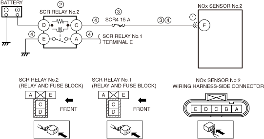
System Wiring Diagram
ac5uuw00009783
|
Function Explanation (DTC Detection Outline)
Repeatability Verification Procedure
1. Perform the "COMPULSORY DIESEL PARTICULATE FILTER REGENERATION". (See COMPULSORY DIESEL PARTICULATE FILTER REGENERATION [SKYACTIV-D 2.2].)
2. Idle the engine for 30 s.
PID Item/Simulation Item Used In Diagnosis
Function Inspection Using M-MDS
|
STEP |
INSPECTION |
RESULTS |
ACTION |
|---|---|---|---|
|
1
|
PURPOSE: VERIFY RELATED REPAIR INFORMATION AVAILABILITY
• Verify related Service Information availability.
• Is any related Service Information available?
|
Yes
|
Perform repair or diagnosis according to the available Service Information.
• If the vehicle is not repaired, go to the next step.
|
|
No
|
Go to the next step.
|
||
|
2
|
PURPOSE: IDENTIFY TRIGGER DTC FOR FREEZE FRAME DATA
• Is the DTC P220B:00 on FREEZE FRAME DATA?
|
Yes
|
Go to the next step.
|
|
No
|
Go to the troubleshooting procedure for DTC on FREEZE FRAME DATA.
|
||
|
3
|
PURPOSE: RECORD FREEZE FRAME DATA/SNAPSHOT DATA AND DIAGNOSTIC MONITORING TEST RESULTS TO UTILIZE WITH REPEATABILITY VERIFICATION
• Recording can be facilitated using the screen capture function of the PC.
• Record the FREEZE FRAME DATA/snapshot data and DIAGNOSTIC MONITORING TEST RESULTS (NOx sensor No.2 related) on the repair order.
|
—
|
Go to Troubleshooting Diagnostic Procedure to perform the procedure from step 1.
|
Troubleshooting Diagnostic Procedure
|
STEP |
INSPECTION |
RESULTS |
ACTION |
|---|---|---|---|
|
1
|
PURPOSE: INSPECT NOx SENSOR NO.2 CONNECTOR CONDITION
• Switch the ignition off.
• Disconnect the NOx sensor No.2 connector.
• Inspect for poor connection (such as damaged/pulled-out pins, corrosion).
• Is there any malfunction?
|
Yes
|
Repair or replace the connector and/or terminals, then go to Step 3.
|
|
No
|
Go to the next step.
|
||
|
2
|
PURPOSE: INSPECT SCR RELAY NO.2
• Switch the ignition off.
• Remove the SCR relay No.2.
(See RELAY LOCATION.)
• Inspect the SCR relay No.2.
(See RELAY INSPECTION.)
• Is there any malfunction?
|
Yes
|
Replace the SCR relay No.2, then go to Step 7.
(See RELAY LOCATION.)
|
|
No
|
Go to the next step.
|
||
|
3
|
PURPOSE: INSPECT SCR4 15 A FUSE
• Remove the SCR4 15 A fuse.
(See RELAY LOCATION.)
• Inspect the SCR4 15 A fuse.
(See RELAY INSPECTION.)
• Is there any malfunction?
|
Yes
|
Go to the next step.
|
|
No
|
If the fuse is blown:
• Refer to the wiring diagram and verify whether or not there is a common connector between SCR4 15 A fuse and NOx sensor No.2 terminal E.
If there is a common connector:
If there is no common connector:
If the fuse is damaged:
• Replace the fuse.
Go to Step 7.
|
||
|
4
|
PURPOSE: INSPECT NOx SENSOR NO.2 CIRCUIT FOR OPEN CIRCUIT
• Verify that the urea level sensor/urea temperature sensor/urea tank heater and dosing control unit connectors are disconnected.
• Switch the ignition off.
• Inspect for continuity between the following terminals (wiring harness-side):
• Is there continuity?
|
Yes
|
Go to the next step.
|
|
No
|
Refer to the wiring diagram and verify whether or not there is a common connector between the following terminals:
• SCR relay No.2 terminal C—NOx sensor No.2 terminal E
• SCR relay No.1 terminal C—SCR relay No.2 terminal A
• SCR relay No.2 terminal E—body ground
If there is a common connector:
• Determine the malfunctioning part by inspecting the common connector and the terminal for corrosion, damage, or pin disconnection, and the common wiring harness for an open circuit.
• Repair or replace the malfunctioning part.
If there is no common connector:
• Repair or replace the wiring harness which has an open circuit.
Go to Step 7.
|
||
|
5
|
PURPOSE: INSPECT DOSING CONTROL UNIT CONNECTOR CONDITION
• Switch the ignition off.
• Disconnect the dosing control unit connector.
• Inspect for poor connection (such as damaged/pulled-out pins, corrosion).
• Is there any malfunction?
|
Yes
|
Repair or replace the connector and/or terminals, then go to Step 7.
|
|
No
|
Go to the next step.
|
||
|
6
|
INSPECT BATTERY
• Inspect the battery.
(See BATTERY INSPECTION.)
• Is there any malfunction?
|
Yes
|
Recharge or replace the battery, then go to the next step.
(See BATTERY RECHARGING.)
|
|
No
|
Replace the NOx sensor No.2, then go to the next step.
|
||
|
7
|
PURPOSE: VERIFICATION OF VEHICLE REPAIR COMPLETION
• Clear the DTC from the dosing control unit memory using the M-MDS.
• Implement the repeatability verification procedure.
• Perform the Pending Trouble Code Access Procedure.
• Is the same Pending DTC present?
|
Yes
|
Repeat the inspection from Step 1.
• If the malfunction recurs, replace the dosing control unit.
Go to the next step.
|
|
No
|
Go to the next step.
|
||
|
8
|
PURPOSE: VERIFY IF THERE IS ANY OTHER MALFUNCTION
• Is any other DTC or pending code stored?
|
Yes
|
Go to the applicable DTC inspection.
|
|
No
|
DTC troubleshooting completed.
|