 |
am6zzw00016351
DTC P0100:00 [PCM (SKYACTIV-G 2.0, SKYACTIV-G 2.5 (WITHOUT CYLINDER DEACTIVATION))]
id0102t1003400
Details On DTCs
|
DESCRIPTION |
Mass air flow sensor circuit performance problem |
|
|---|---|---|
|
DETECTION CONDITION
|
Determination conditions
|
• The following conditions are met:
|
|
Preconditions
|
• The following DTCs are not detected:
• Engine speed: 500 rpm or more
|
|
|
Drive cycle
|
• 1
|
|
|
Self test type
|
• CMDTC self test, KOEO self test, KOER self test
|
|
|
Sensor used
|
• MAF sensor/IAT sensor No.1
|
|
|
FAIL-SAFE FUNCTION
|
• Restricts the upper limit of the engine speed.
• Inhibits the evaporative purge control.
|
|
|
VEHICLE STATUS WHEN DTCs ARE OUTPUT
|
• Illuminates check engine light.
• Rough idling, poor acceleration, stalling
|
|
|
POSSIBLE CAUSE
|
• MAF sensor/IAT sensor No.1 loose
• MAF sensor/IAT sensor No.1 connector or terminals malfunction
• PCM connector or terminals malfunction
• Short to ground in wiring harness between the following terminals:
• Open circuit in wiring harness between the following terminals:
• Short to power supply in wiring harness between MAF sensor/IAT sensor No.1 terminal B and PCM terminal 2BE
• MAF sensor/IAT sensor No.1 circuits are shorted to each other
• MAF sensor/IAT sensor No.1 malfunction
• PCM malfunction
|
|
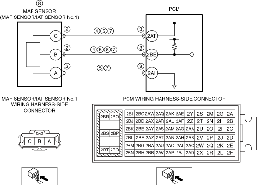
System Wiring Diagram
am6zzw00016351
|
Function Explanation (DTC Detection Outline)
Repeatability Verification Procedure
PID Item/Simulation Item Used In Diagnosis
PID/DATA monitor item table
|
Item |
Definition |
Unit |
Condition/Specification |
|---|---|---|---|
|
MAF
|
Mass air flow input from MAF sensor
|
g/Sec
|
• Displays MAF
|
|
MAF sensor voltage
|
V
|
• Ignition switched ON (engine off) (MAF: 0.00 g/s {0 lb/min}): Approx. 1.69 V (ECT is 53 °C {127 °F})
• Idle (after warm up) (MAF: 2.50 g/s {0.331 lb/min}): Approx. 1.89 V (ECT is 93 °C {199 °F})
• Racing (engine speed is 2,000 rpm) (MAF: 3.80 g/s {0.503 lb/min}): Approx. 2.02 V (ECT is 95 °C {203 °F})
|
|
|
IAT
|
Intake air temperature (No.1) input from IAT sensor No.1
|
°C, °F
|
• Displays IAT (No.1)
|
|
IAT sensor No.1 voltage
|
V
|
• IAT is 20 °C {68 °F}: Approx. 2.70 V
• IAT is 40 °C {104 °F}: Approx. 1.80 V
• IAT is 60 °C {140 °F}: Approx. 1.20 V
|
Function Inspection Using M-MDS
|
STEP |
INSPECTION |
RESULTS |
ACTION |
|---|---|---|---|
|
1
|
PURPOSE: VERIFY RELATED SERVICE INFORMATION AVAILABILITY
• Verify related Service Information availability.
• Is any related Service Information available?
|
Yes
|
Perform repair or diagnosis according to the available Service Information.
• If the vehicle is not repaired, go to the next step.
|
|
No
|
Go to the next step.
|
||
|
2
|
PURPOSE: RECORD VEHICLE STATUS AT TIME OF DTC DETECTION TO UTILIZE WITH REPEATABILITY VERIFICATION
• Record the FREEZE FRAME DATA/snapshot data on the repair order.
|
—
|
Go to the next step.
|
|
3
|
PURPOSE: VERIFY RELATED PENDING CODE AND/OR DTC
• Switch the ignition off, then ON (engine off).
• Perform the Pending Trouble Code Access Procedure and DTC Reading Procedure.
• Are any other PENDING CODEs and/or DTCs present?
|
Yes
|
Go to the applicable PENDING CODE or DTC inspection.
Go to the next step.
|
|
No
|
Go to the next step.
|
||
|
4
|
PURPOSE: VERIFY MAF SENSOR/IAT SENSOR No.1 INPUT SIGNAL
• Start the engine and idle it.
• Access the following PIDs using the M-MDS:
• Is the PID value within specification?
|
Yes
|
Go to the next step.
|
|
No
|
Go to Troubleshooting Diagnostic Procedure to perform the procedure from Step 1.
|
||
|
5
|
PURPOSE: VERIFY CONNECTOR CONNECTIONS
• Start the engine.
• Access the MAF and IAT PID using the M-MDS.
• Does the PID value fluctuate when the following connectors are shaken?
|
Yes
|
Repair or replace the applicable wiring harness or connector parts.
Go to Troubleshooting Diagnostic Procedure to perform the procedure from Step 7.
|
|
No
|
Go to Troubleshooting Diagnostic Procedure to perform the procedure from Step 1.
|
Troubleshooting Diagnostic Procedure
|
STEP |
INSPECTION |
RESULTS |
ACTION |
|---|---|---|---|
|
1
|
INSPECT INSTALLATION OF MAF SENSOR/IAT SENSOR No.1
• Switch the ignition off.
• Inspect installation of MAF sensor/IAT sensor No.1.
• Is the MAF sensor/IAT sensor No.1 installed securely?
|
Yes
|
Go to the next step.
|
|
No
|
Retighten the MAF sensor/IAT sensor No.1, then go to Step 9.
|
||
|
2
|
INSPECT MAF SENSOR/IAT SENSOR No.1 CONNECTOR CONDITION
• Disconnect the MAF sensor/IAT sensor No.1 connector.
• Inspect for poor connection (such as damaged/pulled-out pins, corrosion).
• Is there any malfunction?
|
Yes
|
Repair or replace the connector and/or terminals, then go to Step 9.
|
|
No
|
Go to the next step.
|
||
|
3
|
INSPECT PCM CONNECTOR CONDITION
• Disconnect the PCM connector.
• Inspect for poor connection (such as damaged/pulled-out pins, corrosion).
• Is there any malfunction?
|
Yes
|
Repair or replace the connector and/or terminals, then go to Step 9.
|
|
No
|
Go to the next step.
|
||
|
4
|
INSPECT MAF SENSOR/IAT SENSOR No.1 CIRCUIT FOR SHORT TO GROUND
• Verify that the MAF sensor/IAT sensor No.1 and PCM connectors are disconnected.
• Inspect for continuity between the following terminals (wiring harness-side) and body ground:
• Is there continuity?
|
Yes
|
Refer to the wiring diagram and verify whether or not there is a common connector between the following terminals:
• MAF sensor/IAT sensor No.1 terminal C—PCM terminal 2AT
• MAF sensor/IAT sensor No.1 terminal B—PCM terminal 2BE
If there is a common connector:
• Determine the malfunctioning part by inspecting the common connector and the terminal for corrosion, damage, or pin disconnection, and the common wiring harness for a short to ground.
• Repair or replace the malfunctioning part.
If there is no common connector:
• Repair or replace the wiring harness which has a short to ground.
Go to Step 9.
|
|
No
|
Go to the next step.
|
||
|
5
|
INSPECT MAF SENSOR/IAT SENSOR No.1 CIRCUIT FOR OPEN CIRCUIT
• Verify that the MAF sensor/IAT sensor No.1 and PCM connectors are disconnected.
• Inspect for continuity between the following terminals (wiring harness-side):
• Is there continuity?
|
Yes
|
Go to the next step.
|
|
No
|
Refer to the wiring diagram and verify whether or not there is a common connector between the following terminals:
• MAF sensor/IAT sensor No.1 terminal C—PCM terminal 2AT
• MAF sensor/IAT sensor No.1 terminal B—PCM terminal 2BE
• MAF sensor/IAT sensor No.1 terminal A—PCM terminal 2AI
If there is a common connector:
• Determine the malfunctioning part by inspecting the common connector and the terminal for corrosion, damage, or pin disconnection, and the common wiring harness for an open circuit.
• Repair or replace the malfunctioning part.
If there is no common connector:
• Repair or replace the wiring harness which has an open circuit.
Go to Step 9.
|
||
|
6
|
INSPECT MAF SENSOR/IAT SENSOR No.1 SIGNAL CIRCUIT FOR SHORT TO POWER SUPPLY
• Verify that the MAF sensor/IAT sensor No.1 and PCM connectors are disconnected.
• Switch the ignition ON (engine on).
• Measure the voltage at the MAF sensor/IAT sensor No.1 terminal B (wiring harness-side).
• Is the voltage 0 V?
|
Yes
|
Go to the next step.
|
|
No
|
Refer to the wiring diagram and verify whether or not there is a common connector between MAF sensor/IAT sensor No.1 terminal B and PCM terminal 2BE.
If there is a common connector:
• Determine the malfunctioning part by inspecting the common connector and the terminal for corrosion, damage, or pin disconnection, and the common wiring harness for a short to power supply.
• Repair or replace the malfunctioning part.
If there is no common connector:
• Repair or replace the wiring harness which has a short to power supply.
Go to Step 9.
|
||
|
7
|
INSPECT MAF SENSOR/IAT SENSOR No.1 CIRCUITS FOR SHORT TO EACH OTHER
• Verify that the MAF sensor/IAT sensor No.1 and PCM connectors are disconnected.
• Switch the ignition off.
• Inspect for continuity between MAF sensor/IAT sensor No.1 terminals C, B and A (wiring harness-side).
• Is there continuity?
|
Yes
|
Refer to the wiring diagram and verify whether or not there is a common connector between the following terminals:
• MAF sensor/IAT sensor No.1 terminal C—PCM terminal 2AT
• MAF sensor/IAT sensor No.1 terminal B—PCM terminal 2BE
• MAF sensor/IAT sensor No.1 terminal A—PCM terminal 2AI
If there is a common connector:
• Determine the malfunctioning part by inspecting the common connector and the terminal for corrosion, damage, or pin disconnection, and the common wiring harness for a short to each other.
• Repair or replace the malfunctioning part.
If there is no common connector:
• Repair or replace the wiring harness which has a short to each other.
Go to Step 9.
|
|
No
|
Go to the next step.
|
||
|
8
|
INSPECT MAF SENSOR/IAT SENSOR No.1
• Inspect the MAF sensor/IAT sensor No.1.
• Is there any malfunction?
|
Yes
|
Replace the MAF sensor/IAT sensor No.1, then go to the next step.
|
|
No
|
Go to the next step.
|
||
|
9
|
VERIFY DTC TROUBLESHOOTING COMPLETED
• Always reconnect all disconnected connectors.
• Clear the DTC from the PCM memory using the M-MDS.
• Perform the KOEO or KOER self test.
• Is the same Pending DTC present?
|
Yes
|
Repeat the inspection from Step 1.
• If the malfunction recurs, replace the PCM.
Go to the next step.
|
|
No
|
Go to the next step.
|
||
|
10
|
VERIFY AFTER REPAIR PROCEDURE
• Perform the “AFTER REPAIR PROCEDURE”.
• Are any DTCs present?
|
Yes
|
Go to the applicable DTC inspection.
|
|
No
|
DTC troubleshooting completed.
|