 |
ac8wzw00002721
SUPPLY PUMP REMOVAL/INSTALLATION [SKYACTIV-D 2.2]
id0114z7805700
Replacement Part
|
Clip
Quantity: 5
Location of use: Fuel return pipe (fuel injector side)
|
Injection pipe (supply pump side)
Quantity: 1
Location of use: Supply pump
|
Clip
Quantity: 1
Location of use: Fuel feed pipe
|
|
Washer
Quantity: 2
Location of use: Fuel feed pipe
|
Clip
Quantity: 1
Location of use: Bracket
|
Washer
Quantity: 2
Location of use: Connector No.2
|
|
O-ring
Quantity: 1
Location of use: Supply pump
|
Washer
Quantity: 2
Location of use: Connector No.1
|
Fuel return hose No.2
Quantity: 1
Location of use: Supply pump
|
|
Fuel return hose No.3
Quantity: 1
Location of use: Supply pump
|
—
|
—
|
Oil and Chemical Type
|
Engine oil
Type: Recommended oil
|
Silicone sealant
Type: TB1217D or equivalent
|
Operation After Removed/Installed or Replacing Supply Pump
1. If the supply pump is removed/installed or replaced, perform the following procedure.
|
STEP |
ACTION |
PAGE/CONDITION |
|---|---|---|
|
1
|
Perform supply pump data reset procedure.
|
|
|
2
|
Switch the ignition off.
|
—
|
|
3
|
Wait for 30 s.
|
—
|
|
4
|
Switch the ignition ON (engine off).
|
—
|
|
5
|
Perform KOEO self-test procedure.
|
|
|
6
|
Maintain the idle status for 30 s with the following condition met.
• ECT: 60—100 °C {140—212 °F}
|
—
|
|
7
|
Perform KOER self-test procedure.
|
Supply Pump Removal/Installation
1. Disconnect the negative battery terminal. (See NEGATIVE BATTERY TERMINAL DISCONNECTION/CONNECTION.)
2. Perform the “Fuel Line Safety Procedure” referring to the “BEFORE SERVICE PRECAUTION”. (See BEFORE SERVICE PRECAUTION [SKYACTIV-D 2.2].)
3. Remove the engine cover. (See ENGINE COVER REMOVAL/INSTALLATION [SKYACTIV-D 2.2].)
4. Remove the air cleaner. (See INTAKE-AIR SYSTEM REMOVAL/INSTALLATION [SKYACTIV-D 2.2].)
5. Remove the battery and the battery tray. (See BATTERY REMOVAL/INSTALLATION [SKYACTIV-D 2.2].)
6. Remove the following parts as a single unit: (See INTAKE-AIR SYSTEM REMOVAL/INSTALLATION [SKYACTIV-D 2.2].)
7. Disconnect the breather from the cylinder head cover. (See INTAKE-AIR SYSTEM REMOVAL/INSTALLATION [SKYACTIV-D 2.2].)
8. Disconnect the blow-by heater connector. (See INTAKE-AIR SYSTEM REMOVAL/INSTALLATION [SKYACTIV-D 2.2].)
9. Remove the turbocharger air inlet pipe and breather hose as single unit. (See INTAKE-AIR SYSTEM REMOVAL/INSTALLATION [SKYACTIV-D 2.2].)
10. Remove the nuts and set the turbocharger air outlet pipe component aside. (See INTAKE-AIR SYSTEM REMOVAL/INSTALLATION [SKYACTIV-D 2.2].)
ac8wzw00002721
|
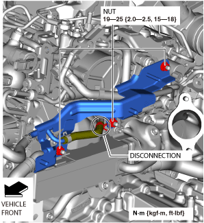
11. Set the water pipe assy aside as shown in the figure.
ac8wzw00002722
|
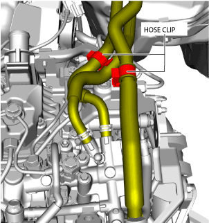
12. Detach the hose clip shown in the figure.
ac8wzw00002723
|
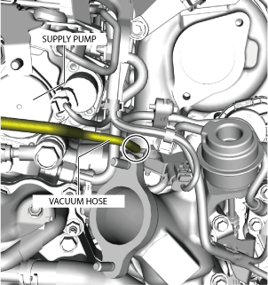
13. Disconnect the vacuum hose shown in the figure.
ac8wzw00002724
|
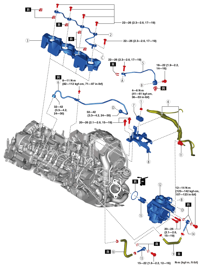
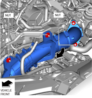
14. Remove in the order shown in the figure.
15. Install in the reverse order of removal.
16. Perform the fuel hose installation procedure and fuel line air bleeding referring to the “AFTER SERVICE PRECAUTION”. (See AFTER SERVICE PRECAUTION [SKYACTIV-D 2.2].)
am6zzw00018177
|
|
1
|
Clip installation nut
|
|
2
|
Fuel return pipe (fuel injector side)
|
|
3
|
Cover
|
|
4
|
Wiring harness clip
|
|
5
|
Fuel feed pipe
|
|
6
|
Injection pipe (supply pump side)
|
|
7
|
Clip
|
|
8
|
Bracket
|
|
9
|
Fuel return hose No.3
|
|
10
|
Fuel return hose No.2
|
|
11
|
Suction control valve connector
|
|
12
|
Supply pump
|
|
13
|
Connector No.1
|
|
14
|
Connector No.2
|
|
15
|
Spacer
|
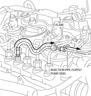
Injection pipe (supply pump side) removal note
1. Remove the injection pipe (supply pump side) as shown in the figure. (See INJECTION PIPE REMOVAL/INSTALLATION [SKYACTIV-D 2.2].)
ac5wzw00005720
|
2. Remove the injection pipe (supply pump side).
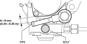
Connector No.1 installation note
1. Install the connector No.1 as shown in the figure so that the pipe does not cover the bolt.
ac5wzw00007124
|
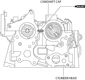
Supply pump installation note
1. Apply silicone sealant (TB1217D or equivalent) to the areas shown in the figure.
ac5wzw00007971
|
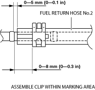
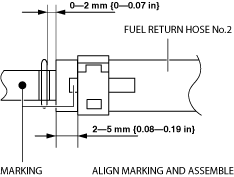
Fuel return hose No.2 installation note
1. Install fuel return hose No.2 as shown in the figure.
Supply pump side
ac8wzw00002726
|
Lower case side
ac8wzw00002727
|
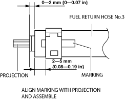
Fuel return hose No.3 installation note
1. Install fuel return hose No.3 as shown in the figure.
Supply pump side
ac8wzw00002728
|
Lower case side
ac8wzw00002729
|
Injection pipe (supply pump side) installation note
1. Install the injection pipe (supply pump side) as shown in the figure. (See INJECTION PIPE REMOVAL/INSTALLATION [SKYACTIV-D 2.2].)
ac5wzw00007972
|