 |
ac8wzw00002735
INJECTION PIPE REMOVAL/INSTALLATION [SKYACTIV-D 2.2]
id0114z7850200
Replacement Part
|
Injection pipe (fuel injector side)
Quantity: 1
Location of use: Common rail
|
Injection pipe (supply pump side)
Quantity: 1
Location of use: Common rail
|
1. Disconnect the negative battery terminal. (See NEGATIVE BATTERY TERMINAL DISCONNECTION/CONNECTION.)
2. Perform the “Fuel Line Safety Procedure” referring to the “BEFORE SERVICE PRECAUTION”. (See BEFORE SERVICE PRECAUTION [SKYACTIV-D 2.2].)
3. Remove the engine cover. (See ENGINE COVER REMOVAL/INSTALLATION [SKYACTIV-D 2.2].)
4. Remove the fuel return pipe (fuel injector side) and cover. (See FUEL INJECTOR REMOVAL/INSTALLATION [SKYACTIV-D 2.2].)
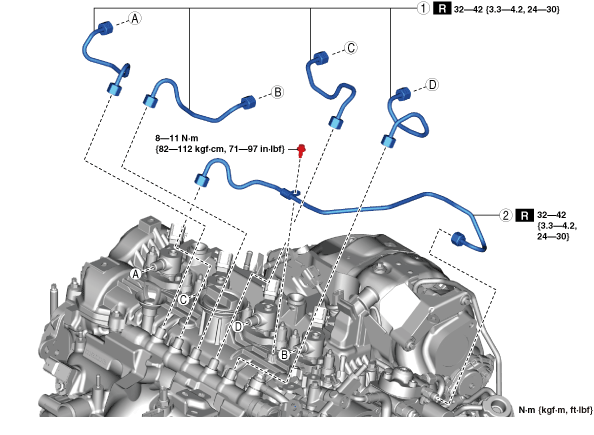
5. Remove in the order shown in the figure.
6. Install in the reverse order of removal.
7. Perform the “Fuel Hose Installation Procedure” and “Fuel Line Air Bleeding” referring to the “AFTER SERVICE PRECAUTION”. (See AFTER SERVICE PRECAUTION [SKYACTIV-D 2.2].)
ac8wzw00002735
|
|
1
|
Injection pipe (fuel injector side)
|
|
2
|
Injection pipe (supply pump side)
|
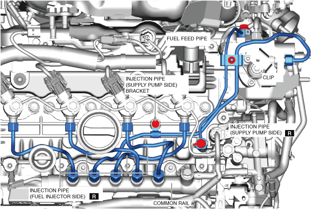
Injection Pipe (Supply Pump Side) Removal Note
1. Remove the battery and battery tray. (See SUPPLY PUMP REMOVAL/INSTALLATION [SKYACTIV-D 2.2].)
2. Remove the air inlet pipe. (See INTAKE-AIR SYSTEM REMOVAL/INSTALLATION [SKYACTIV-D 2.2].)
3. Disconnect the blow-by heater connector. (See INTAKE-AIR SYSTEM REMOVAL/INSTALLATION [SKYACTIV-D 2.2].)
4. Disconnect the breather hose from the cylinder head cover. (See INTAKE-AIR SYSTEM REMOVAL/INSTALLATION [SKYACTIV-D 2.2].)
5. Remove the turbocharger air inlet pipe and breather hose as single unit. (See INTAKE-AIR SYSTEM REMOVAL/INSTALLATION [SKYACTIV-D 2.2].)
6. Remove the fuel feed pipe. (See INTAKE-AIR SYSTEM REMOVAL/INSTALLATION [SKYACTIV-D 2.2].)
7. Remove the injection pipe (supply pump side).
Injector Pipe Installation Note
1. Loosen the common rail.
ac8wzw00002736
|
2. Temporarily tighten the new injection pipe (supply pump side).
3. Temporarily tighten the new injection pipes (fuel injector side).
4. Temporarily install the fuel return pipe (supply pump side).
5. Tighten the clip.
6. Tighten the injection pipe (supply pump side) bracket.
7. Tighten the injection pipe (supply pump side) and the injection pipes (fuel injector side) on the common rail side.
8. Tighten the injection pipe (supply pump side) and the injection pipes (fuel injector side) on the fuel injector side.
9. Tighten the common rail.
10. Tighten the fuel feed pipe.