 |
ac5wzw00009753
CRUISE CONTROL SWITCH INSPECTION [SKYACTIV-G 2.5 (WITH CYLINDER DEACTIVATION)]
id0120q6800100
1. Disconnect the negative battery terminal and wait for 1 min or more. (See NEGATIVE BATTERY TERMINAL DISCONNECTION/CONNECTION.)
2. Remove the driver-side air bag module. (See DRIVER-SIDE AIR BAG MODULE REMOVAL [STANDARD DEPLOYMENT CONTROL SYSTEM].) (See DRIVER-SIDE AIR BAG MODULE INSTALLATION [STANDARD DEPLOYMENT CONTROL SYSTEM].) (See DRIVER-SIDE AIR BAG MODULE REMOVAL [TWO-STEP DEPLOYMENT CONTROL SYSTEM].) (See DRIVER-SIDE AIR BAG MODULE INSTALLATION [TWO-STEP DEPLOYMENT CONTROL SYSTEM].)
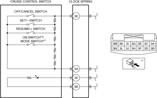
3. Disconnect the clock spring connector (part wiring harness-side).
4. Measure the resistance between clock spring terminals 3E and 3A (part wiring harness-side) using a tester.
ac5wzw00009753
|
|
Switch condition |
Resistance (ohm) |
|---|---|
|
OFF/CANCEL switch held at on
|
Continuity
|
|
SET/− switch held at on
|
Approx. 84.5
|
|
RESUME/+ switch held at on
|
Approx. 189.5
|
|
ON switch held at on (without adjustable speed limiter)
MODE switch held at on (with adjustable speed limiter)
|
Approx. 326.5
|
|
Neutral
|
Approx. 3,311.5
|
5. Apply battery positive voltage to clock spring terminal 3F (part wiring harness-side), and terminal 3B (part wiring harness-side) to ground.
am3uuw00012307
|
6. Verify that the LED in the steering switch turns on.