CRANKSHAFT POSITION (CKP) SENSOR INSPECTION [SKYACTIV-G 2.0, SKYACTIV-G 2.5 (WITHOUT CYLINDER DEACTIVATION)]


id0140h4800500


Visual Inspection

Caution
•  If foreign matter such as metal shaving adhere to the CKP sensor, it can cause abnormal output from the sensor because of flux turbulence, which can negatively affect the engine control. Verify that there is no foreign matter on the CKP sensor when replacing.
•  Do not assemble the CKP sensor or change the installation position using any method other than the following. Otherwise, it could negatively affect engine control, such as the ignition timing and fuel injection.

1.  Disconnect the negative battery terminal. (See NEGATIVE BATTERY TERMINAL DISCONNECTION/CONNECTION.)

2.  Lift up the vehicle.

3.  Remove the following parts for easier access.

(1)  Service hole cover (installed to front under cover No.2) used to remove the oil filter (See OIL FILTER REPLACEMENT [SKYACTIV-G 2.0, SKYACTIV-G 2.5 (WITHOUT CYLINDER DEACTIVATION)].)
(2)  Front splash shield (RH) (See SPLASH SHIELD REMOVAL/INSTALLATION.)

4.  Disconnect the CKP sensor connector.

5.  Remove the CKP sensor. (See CRANKSHAFT POSITION (CKP) SENSOR REMOVAL/INSTALLATION [SKYACTIV-G 2.0, SKYACTIV-G 2.5 (WITHOUT CYLINDER DEACTIVATION)].)

6.  Verify that there are no metal shavings on the sensor.
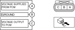
•  If there is a malfunction, remove any metal shavings that are adhering.


Voltage Inspection

Caution
•  If foreign matter such as metal shaving adhere to the CKP sensor, it can cause abnormal output from the sensor because of flux turbulence, which can negatively affect the engine control. Verify that there is no foreign matter on the CKP sensor when replacing.
•  Do not assemble the CKP sensor or change the installation position using any method other than the following. Otherwise, it could negatively affect engine control, such as the ignition timing and fuel injection.
•  If the wiring harnesses or waterproof connectors are damaged, water penetrating the connector will cause a sensor malfunction. To prevent this, be careful not to damage wiring harnesses or waterproof connectors.

1.  Idle the engine.

2.  Measure the CKP sensor output voltage wave pattern using an oscilloscope.

ac5uuw00007956
•  Specification
4.5 V or more (Maximum value of wave pattern)
0.8 V or less (Minimum value of wave pattern)

Wave pattern (reference)

adejjw00007912
Oscilloscope setting
•  2 V/DIV (Y), 1 ms/DIV (X), DC range
Vehicle condition
•  Idle (after warm up)