 |
am6xuw00010910
PM SENSOR REMOVAL/INSTALLATION [SKYACTIV-D 2.2]
id0140z7825900
1. Disconnect the negative battery terminal. (See NEGATIVE BATTERY TERMINAL DISCONNECTION/CONNECTION.)
2. Remove the floor under cover No.1 and floor under cover No.2. (See FLOOR UNDER COVER REMOVAL/INSTALLATION.)
3. Remove the following parts: (See EXHAUST SYSTEM REMOVAL/INSTALLATION [SKYACTIV-D 2.2].)
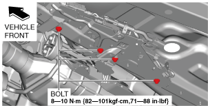
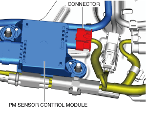
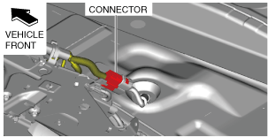
4. Disconnect the connector shown in the figure.
am6xuw00010910
|
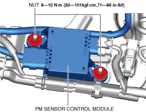
5. Remove the bolts shown in the figure.
am6xuw00010911
|
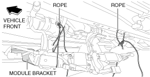
6. Suspend module bracket using a rope as shown in the figure.
am6xuw00012232
|
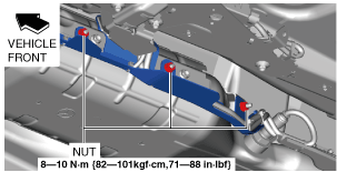
7. Remove the nuts shown in the figure.
am6xuw00010912
|
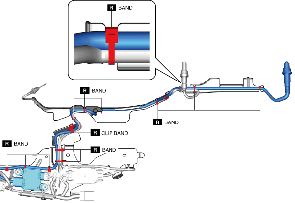
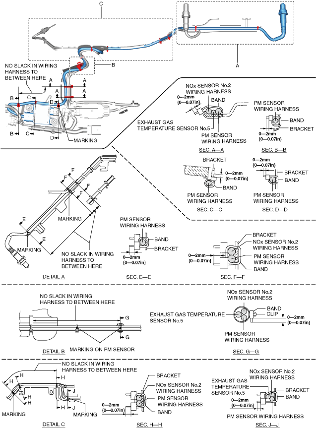
8. Cut the bands and clip band shown in the figure. (See Band Installation Note.)
am6xuw00010913
|
9. Remove the PM sensor control module from the module bracket.
am6xuw00010914
|
10. Disconnect the connector shown in the figure.
am6xuw00010730
|
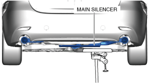
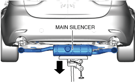
11. Support the main silencer using a transmission jack.
am6xuw00010915
|
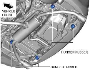
12. Remove the hunger rubber.
am6xuw00010916
|
13. Lower the transmission jack slowly to a position allowing removal of the PM sensor.
am6xuw00010731
|
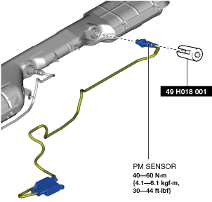
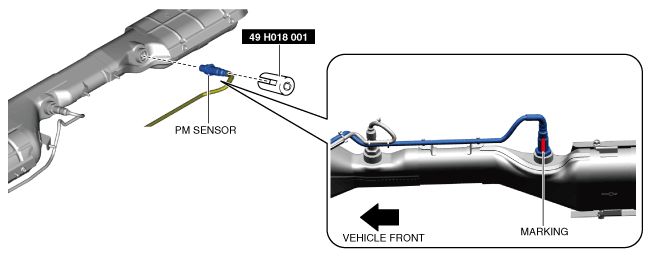
14. Remove the PM sensor using the SST.
am6xuw00013037
|
15. Install in the reverse order of removal.(See PM Sensor Installation Note.)
Band Installation Note
1. Install bands as shown in the figure.
am6zzw00017031
|
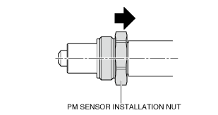
PM Sensor Installation Note
1. Slide the PM sensor installation nut in the direction shown in the figure.
ac5wzw00014319
|
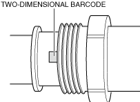
2. Verify the two-dimensional barcode.
ac5wzw00014320
|
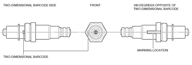
3. Mark the PM sensor at the position 180 degrees opposite of the two-dimensional barcode as shown in the figure.
am6zzw00018492
|
4. Using the SST, assemble the PM sensor so that the marking placed in Step 3 is facing the ground.
am6zzw00018485
|
5. Verify the direction the PM sensor marking is facing.