 |
am6zzn00003222
ON-BOARD DIAGNOSTIC SYSTEM [ELECTRONIC 4WD CONTROL SYSTEM]
id0302a6108100
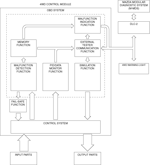
Outline
Block diagram
am6zzn00003222
|
Function
Malfunction detection function
Malfunction indication function
Memory function
DTC table
|
DTC |
4WD warning light |
Description |
Fail-safe |
Drive cycle |
Self test type*1 |
Memory function |
|---|---|---|---|---|---|---|
|
P164D:00
|
Illuminates
|
4WD control module configuration
|
×
|
—
|
C
|
×
|
|
P182F:00
|
Flashes
|
4WD control module
|
×
|
—
|
C
|
×
|
|
P187B:00
|
Illuminates
|
4WD control module
|
×
|
—
|
C
|
×
|
|
P1886:00
|
Illuminates
|
4WD control module
|
×
|
—
|
C
|
×
|
|
P1887:11
|
Illuminates
|
System wiring
|
×
|
—
|
C
|
×
|
|
P1887:12
|
Illuminates
|
System wiring
|
×
|
—
|
C
|
×
|
|
P1887:13
|
Illuminates
|
System wiring
|
×
|
—
|
C
|
×
|
|
P1887:14
|
Illuminates
|
System wiring
|
×
|
—
|
C
|
×
|
|
P1888:11
|
Illuminates
|
Differential oil temperature sensor
|
×
|
—
|
C
|
×
|
|
P1888:15
|
Illuminates
|
Differential oil temperature sensor
|
×
|
—
|
C
|
×
|
|
P188A:00
|
Flashes
|
4WD control module
|
×
|
—
|
C
|
×
|
|
U0001:88
|
Illuminates
|
CAN line
|
×
|
—
|
C
|
×
|
|
U0100:00
|
Not illuminate
|
CAN line
|
×
|
—
|
C
|
×
|
|
U0101:00*2
|
Not illuminate
|
CAN line
|
×
|
—
|
C
|
×
|
|
U0121:00
|
Not illuminate
|
CAN line
|
×
|
—
|
C
|
×
|
|
U0401:68
|
Not illuminate
|
Signal error from PCM
|
×
|
—
|
C
|
×
|
|
U0402:68*2
|
Not illuminate
|
Signal error from TCM
|
×
|
—
|
C
|
×
|
|
U0415:68
|
Not illuminate
|
Signal error from DSC HU/CM
|
×
|
—
|
C
|
×
|
|
U2100:00
|
Illuminates
|
4WD control module configuration
|
×
|
—
|
C
|
×
|
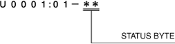
Status byte for DTC
am2zzn00002656
|
Fail-safe function
Fail-safe function table
|
DTC |
4WD control |
|---|---|
|
P164D:00
|
Control maintained by the specified data
|
|
P182F:00
|
Control paused (4WD protection condition)
|
|
P187B:00
|
Control paused (4WD protection condition)
|
|
P1886:00
|
Control disabled
|
|
P1887:11
|
Control disabled
|
|
P1887:12
|
Control disabled
|
|
P1887:13
|
Control disabled
|
|
P1887:14
|
Control disabled
|
|
P1888:11
|
Control disabled
|
|
P1888:15
|
Control disabled
|
|
P188A:00
|
Control paused (4WD protection condition)
|
|
U0001:88
|
Control disabled
|
|
U0100:00
|
Control disabled
|
|
U0101:00
|
Lost gear position signal: Control maintained by the specified data
Except above: Control disabled
|
|
U0121:00
|
Control disabled
|
|
U0401:68
|
Control disabled
|
|
U0402:68
|
Control maintained by the specified data
|
|
U0415:68
|
Control disabled
|
|
U2100:00
|
Control maintained by the specified data
|
Snapshot data
|
Snapshot data item |
Unit |
Definition |
Data read/use method |
Corresponding data monitor items |
|
|---|---|---|---|---|---|
|
AAT
|
°C
|
°F
|
Ambient air temperature
|
—
|
AAT
|
|
IC_VPWR
|
V
|
Instrument cluster power supply
|
• The 4WD control module constantly receives the power supply voltage value of the instrument cluster sent via CAN signal from the instrument cluster.
• If a DTC is detected, the 4WD control module records the power supply voltage of the instrument cluster when the DTC was detected, and it is displayed in the Mazda Modular Diagnostic System (M-MDS).
|
VPWR*1
|
|
|
IG-ON_TIMER
|
hh:mm:ss*2
|
Elapsed time since ignition was switched ON
|
• The 4WD control module constantly receives the elapsed time since the ignition was switched ON sent via CAN signal from the instrument cluster.
• If a DTC is detected, the 4WD control module records the elapsed time since the ignition was switched ON when the DTC was detected, and it is displayed in the Mazda Modular Diagnostic System (M-MDS).
|
—
|
|
|
PWR_MODE_KEY
|
Key Out/Key Recently Out/Key Approved (Position 0)/Post Accessory (Position 0)/Accessory (Position 1)/Post Ignition (Position 1)ignition On (Position 2)/Running (Position 2)/Running - Starting In Progr
|
Ignition switch status
|
• The 4WD control module constantly receives the ignition switch status sent via CAN signal from the instrument cluster.
• If a DTC is detected, the 4WD control module records the ignition switch status when the DTC was detected, and it is displayed in the Mazda Modular Diagnostic System (M-MDS).
|
—
|
|
|
TOTAL_DIST
|
km
|
ft, mi
|
Accumulated total traveled distance from completion of vehicle until 4WD control module detects DTC (Odometer value in instrument cluster)
|
The distance traveled when the 4WD control module detected a DTC can be calculated by performing the following procedure.
1. Verify the odometer value in the instrument cluster.
2. Verify the snapshot data item TOTAL_DIST.
3. Subtract 2 from 1.
|
—
|
|
TOTAL_TIME
|
hh:mm:ss*2
|
Accumulated total elapsed time since vehicle completion until 4WD control module detects a DTC
|
The elapsed time when the 4WD control module detected a DTC can be calculated by performing the following procedure.
1. Verify the PID item TOTAL_TIME of the instrument cluster.
2. Verify the snapshot data item TOTAL_TIME.
3. Subtract 2 from 1.
|
TOTAL_TIME*1
|
|
PID/data monitor function
|
Monitor item |
Unit/Operation |
Definition |
|---|---|---|
|
Mazda Modular Diagnostic System (M-MDS) display |
||
|
AAT
|
°C, °F
|
This PID indicates ambient air temperature.
|
|
APP
|
%
|
This PID indicates accelerator pedal position.
|
|
CAL_TABLE
|
—
|
This PID indicates 4WD calibration table.
|
|
CUP_SOL
|
%
|
This PID indicates 4WD solenoid duty cycle.
|
|
GEAR
|
Unknown/1st/2nd/3rd/4th/5th/6th/7th/8th/Not in P/Park/Neutral/Drive/Reverse
|
This PID indicates gear position.
|
|
OIL_TEMP
|
°C, °F
|
This PID indicates differential oil temperature.
|
|
RPM
|
RPM
|
This PID indicates engine speed.
|
|
SHIFT
|
2Positions/P/R/N/D/S(2)/L(1)/-
|
This PID indicates select lever position.
|
|
TORQUE
|
Nm
|
This PID indicates total wheel torque.
|
|
VPWR
|
V
|
This PID indicates power supply voltage for 4WD control module.
|
|
WARN_LAMP
|
OFF/Blinking/ON
|
This PID indicates 4WD warning light status.
|
|
WSPD_LF
|
KPH, MPH
|
This PID indicates wheel speed.
|
|
WSPD_LR
|
KPH, MPH
|
This PID indicates wheel speed.
|
|
WSPD_RF
|
KPH, MPH
|
This PID indicates wheel speed.
|
|
WSPD_RR
|
KPH, MPH
|
This PID indicates wheel speed.
|
Simulation function
|
Simulation item |
Output part |
Operation |
Operating condition |
|---|---|---|---|
|
CUP_SOL
|
4WD solenoid
|
OFF/ON
|
Switch the ignition ON (engine off or on)
|
External tester communication function
|
Diagnostic function name |
Signal received |
Signal sent |
|---|---|---|
|
Malfunction detection function
|
DTC verification signal
|
DTC(s)
|
|
PID/data monitor function
|
Command signal to read selected monitor item
|
Monitored data for requested monitor item
|
|
Simulation function
|
Operation command signal for selected simulation item
|
Output part drive signal
|