PROPELLER SHAFT REMOVAL/INSTALLATION
id031500149300
-
Caution
-
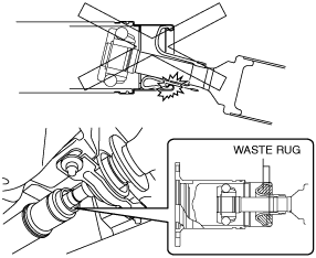
• If the constant velocity joint is bent during propeller shaft removal/installation or transportation after servicing, the constant velocity joint boot may contact the metallic cover and the boot may be damaged. Insert a rag between the boot and the metallic cover before servicing to protect the boot
1. Remove the following parts: (See FLOOR UNDER COVER REMOVAL/INSTALLATION.)
- (1) Floor under cover No.2
-
- (2) Floor under cover No.1
-
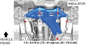
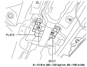
2. Remove the fasteners and bolt in the order shown in the figure.
3. Remove the insulator.
4. Remove the following parts: (See EXHAUST SYSTEM REMOVAL/INSTALLATION [SKYACTIV-D 2.2].)
- (1) Brace bar
-
- (2) Tunnel member
-
5. For SKYACTIV-D 2.2 (Without SCR system) vehicles, perform the following procedure.
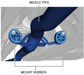
- (1) Remove the middle pipe from the mount rubber.
-
- (2) Disconnect the middle pipe from the main silencer. (See EXHAUST SYSTEM REMOVAL/INSTALLATION [SKYACTIV-D 2.2].)
-
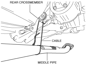
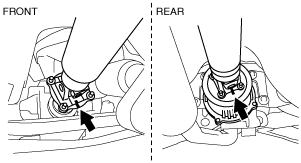
- (3) Suspend the middle pipe using a cable as shown in the figure.
-
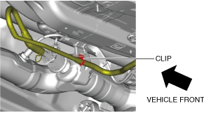
6. For SKYACTIV-D 2.2 (With SCR system) vehicles, perform the following procedure.
- (1) Remove the clip.
-
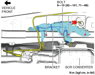
- (2) Remove the bolts.
-
- (3) Set the bracket aside.
-
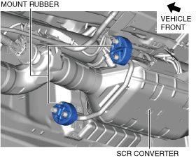
- (4) Remove the SCR converter from the mount rubber.
-
- (5) Disconnect the SCR converter from the main silencer. (See EXHAUST SYSTEM REMOVAL/INSTALLATION [SKYACTIV-D 2.2].)
-
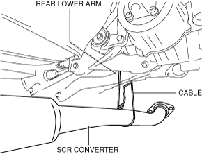
- (6) Suspend the SCR converter using a cable as shown in the figure.
-
7. Remove the plate shown in the figure. (With plate) (See Plate Installation Note.)
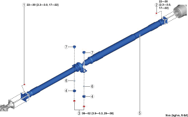
8. Remove in the order indicated in the figure.
9. Install in the reverse order of removal.
10. Perform a road test and verify that there is no abnormal vibration or noise.
|
1
|
Nut (front)
|
|
2
|
Nut (rear)
|
|
3
|
Nut (center bearing support)
|
|
4
|
Bush (lower)
|
|
5
|
Propeller shaft
|
|
6
|
Washer
|
|
7
|
Bush (upper)
|
Propeller Shaft Removal Note
-
Caution
-
• Do not mark with a punch to prevent imbalance.
1. Before removing the nut, place alignment marks on the companion flange (front) and constant velocity joint, and on the coupling component (rear) and yoke.
2. Loosen the nuts (front, rear, center bearing support).
3. Remove the front and rear nuts.
-
Caution
-
• Propeller shaft is attached to the stud.
4. Press the propeller shaft and remove it from the rear side.
-
Caution
-
• Do not bend the propeller shaft to the extent that it interferes with the boot.
5. Remove the center bearing support nut, then remove the propeller shaft
Propeller Shaft Installation Note
-
Caution
-
• If the nuts are loosened, verify that the stud bolt tightening torque against the coupling is 6.4 N·m {65 kgf·cm, 57 in·lbf} or more. If the tightening torque is less than 6.4 N·m {65 kgf·cm, 57 in·lbf}, tighten the stud bolt with 6.4—9.6 N·m {66—97 kgf·cm, 57—84 in·lbf}.
• When loosening the nut, if a nut is stuck to a stud bolt, replace the stud bolt with a new one.
• When replacing the stud bolts, clean off oil and foreign matter on the bolts and coupling installation areas in advance.
-
Note
-
• The stud bolts are entirely threaded with no front/rear distinction.
1. Degrease the tightening area.
2. Align the alignment marks, and temporarily install the nuts (front, rear, center bearing support).
-
Caution
-
• Do not bend the propeller shaft to the extent that it interferes with the boot.
3. Tighten the nut (front) with specified torque first, and then install the other nuts.
Plate Installation Note
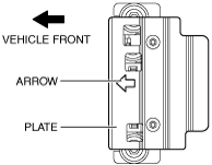
1. Install the plate so that the arrow shown in the figure is pointed toward the vehicle front.