 |
ac5wzw00006718
SHIFT CONTROL MODULE REMOVAL/INSTALLATION [D66M-R, D66MX-R]
id0515md160200
1. Shift the shift lever to the neutral position.
2. Disconnect the negative battery terminal. (See NEGATIVE BATTERY TERMINAL DISCONNECTION/CONNECTION.)
3. Remove the engine cover. (See ENGINE COVER REMOVAL/INSTALLATION [SKYACTIV-D 2.2].)
4. Remove the front under cover No.2. (See FRONT UNDER COVER No.2 REMOVAL/INSTALLATION.)
5. Remove the following parts as a single unit. (See INTAKE-AIR SYSTEM REMOVAL/INSTALLATION [SKYACTIV-D 2.2].)
6. Remove the battery and battery tray. (See BATTERY REMOVAL/INSTALLATION [SKYACTIV-D 2.2].)
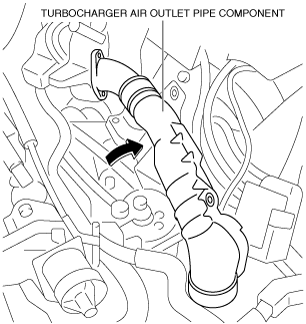
7. Set the turbocharger air outlet pipe component aside as a single unit as shown in the figure. (See INTAKE-AIR SYSTEM REMOVAL/INSTALLATION [SKYACTIV-D 2.2].)
ac5wzw00006718
|
8. Disconnect the control cable from the manual transaxle. (See MANUAL TRANSAXLE SHIFT MECHANISM REMOVAL/INSTALLATION [D66M-R, D66MX-R].)
9. Remove the neutral switch. (See NEUTRAL SWITCH REMOVAL/INSTALLATION [D66M-R, D66MX-R].)
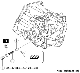
10. Remove the detent ball pin in the order shown in the figure.
ac5wzw00009154
|
|
1
|
Plug
|
|
2
|
Gasket
|
|
3
|
Spring
|
|
4
|
Detent ball pin
|
11. Remove the back-up light switch. (See BACK-UP LIGHT SWITCH REMOVAL/INSTALLATION [D66M-R, D66MX-R].)
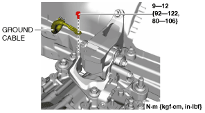
12. Remove the bolt shown in the figure and set the ground cable aside.
am6zzw00016458
|
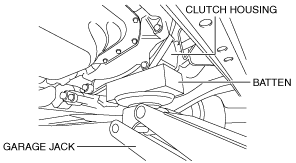
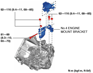
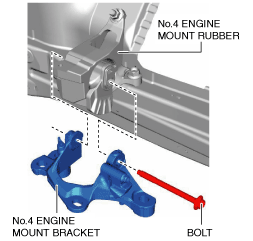
13. Remove the No.4 engine mount bracket using the following procedure. (See No.4 Engine Mount Bracket Installation Note.)
ac5wzw00005924
|
ac5wzw00009156
|
ac5wzw00009495
|
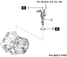
14. Remove the shift control module in the order shown in the figure.
ac5wzw00009157
|
|
1
|
Breather
|
|
2
|
Shift control module
|
|
3
|
O-ring
|
15. Install in the reverse order of removal.
Shift Control Module Installation Note
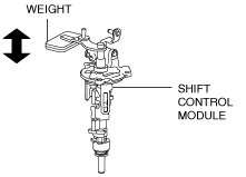
1. Verify that the shift control module is in the neutral position.
ac5wzw00005929
|
2. Install the shift control module.
No.4 Engine Mount Bracket Installation Note
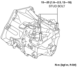
1. Tighten the stud bolts.
ac5wzw00010737
|
2. Install the No.4 engine mount bracket to No.4 engine mount rubber, and temporarily tighten the installation bolt.
am6zzw00016459
|
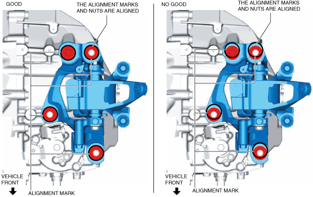
3. Align the positions of the No.4 engine mount bracket installation nuts and bolt with the No.4 engine mount bracket, and temporarily tighten the No.4 engine mount bracket installation nuts and bolt.
ac5wzw00009159
|
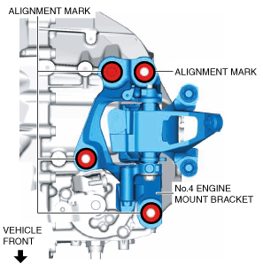
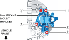
4. Tighten the No.4 engine mount bracket installation nuts and bolts in the order shown in the figure.
ac5wzw00009496
|
|
No. |
Tightening torque |
|---|---|
|
1
|
92—116 N·m {9.4—11 kgf·m, 68—85 ft·lbf}
|
|
2
|
81—99 N·m {8.3—10 kgf·m, 60—73 ft·lbf}
|
Control Cable Ends (Transaxle Side) Installation Note
1. Verify that the shift control module is in the neutral position.
2. Connect the control cable to the manual transaxle. (See MANUAL TRANSAXLE SHIFT MECHANISM REMOVAL/INSTALLATION [D66M-R, D66MX-R].)
3. Make sure that the shift lever can be shifted smoothly.