ac5wzw00004633
|
MANUAL TRANSAXLE SHIFT MECHANISM REMOVAL/INSTALLATION [D66M-R, D66MX-R]
id0516cb160800
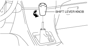
Shift Lever Removal/Installation
1. Disconnect the negative battery terminal. (See NEGATIVE BATTERY TERMINAL DISCONNECTION/CONNECTION.)
2. Remove the following parts:
ac5wzw00004633
|
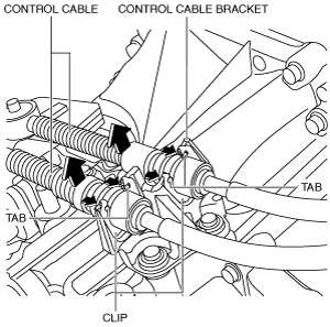
3. Press the tabs on the control cables as shown in the figure and disconnect the control cables from the shift lever. (See Control cables (shift lever side) installation note.)
ac5uuw00000763
|
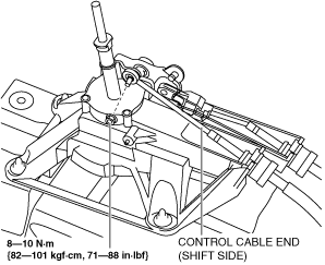
4. Disconnect the control cable end (shift side) from the shift lever as shown in the figure. (See Control cables (shift lever side) installation note.)
am3zzw00016532
|
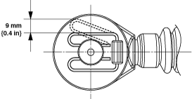
5. Press down the safety lock in the direction shown in the figure.
am6zzw00008418
|
6. Push out the lock piece in the direction shown in the figure.
7. Disconnect the control cable end (select side) from the shift lever. (See Control cables (shift lever side) installation note.)
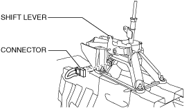
8. Disconnect the connector from the shift lever as shown in the figure.
ac5uuw00000765
|
9. Remove the rear vent duct. (With rear vent) (See REAR VENT DUCT REMOVAL/INSTALLATION.)
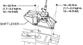
10. Remove the shift lever.
ac5uuw00000766
|
11. Install in the reverse order of removal.
Control cables (shift lever side) installation note
1. Verify that the shift lever is in the neutral position.
2. Connect the control cables to the shift lever.
am3zzw00016530
|
3. Connect the control cable end (shift side) to the shift lever as shown in the figure.
am3zzw00016532
|
4. Verify that the shift lever and the manual transaxle are in the neutral position.
5. Shift the shift lever to fourth gear.
6. Press in the lock piece in the direction shown in the figure. (1 in Fig.)
am3zzw00016529
|
7. Press up the safety lock in the direction shown in the figure. (2 in Fig.)
Control Cable Removal/Installation
1. Disconnect the negative battery terminal. (See NEGATIVE BATTERY TERMINAL DISCONNECTION/CONNECTION.)
2. Perform the following procedure to remove the control cables (shift lever side).
ac5wzw00004633
|
ac5uuw00000763
|
am3zzw00016532
|
am6zzw00008418
|
3. Perform the following procedure to remove the control cables (transaxle side).
ac5uuw00009243
|
ac5uuw00000767
|
am6zzw00015625
|
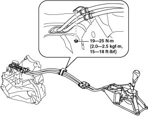
4. Remove the fastening nut for the control cables.
am3zzw00016526
|
5. Remove the fastening nuts for the grommet.
ac5uuw00000770
|
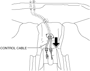
6. Remove the control cable.
ac5uuw00000771
|
7. Install in the reverse order of removal.
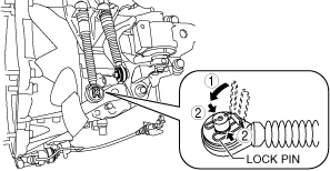
Control cable ends (transaxle side) installation note
1. Verify that the shift control module is in the neutral position.
ac5uuw00009244
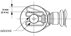
|
2. Install the lock pin to the groove of the control cable end.
am3zzw00016533
|
3. Connect the control cable end to the manual transaxle.
Control cables (shift lever side) installation note
1. Verify that the shift lever is in the neutral position.
2. Connect the control cables to the shift lever.
am3zzw00016530
|
3. Connect the control cable end (shift side) to the shift lever as shown in the figure.
am3zzw00016532
|
4. Verify that the shift lever and the manual transaxle are in the neutral position.
5. Shift the shift lever to fourth gear.
6. Press in the lock piece in the direction shown in the figure. (1 in Fig.)
am3zzw00016529
|
7. Press up the safety lock in the direction shown in the figure. (2 in Fig.)