 |
am3uuw00008326
OIL SEAL (CONTROL VALVE BODY) REPLACEMENT [FW6A-EL]
id0517h1118700
1. Disconnect the negative battery terminal. (See NEGATIVE BATTERY TERMINAL DISCONNECTION/CONNECTION.)
2. Remove the plug hole plate. (See PLUG HOLE PLATE REMOVAL/INSTALLATION [SKYACTIV-G 2.0, SKYACTIV-G 2.5 (WITHOUT CYLINDER DEACTIVATION)].) (See PLUG HOLE PLATE REMOVAL/INSTALLATION [SKYACTIV-G 2.5 (WITH CYLINDER DEACTIVATION)].)
3. Remove the following parts as a single unit. (See INTAKE-AIR SYSTEM REMOVAL/INSTALLATION [SKYACTIV-G 2.0, SKYACTIV-G 2.5 (WITHOUT CYLINDER DEACTIVATION)].) (See INTAKE-AIR SYSTEM REMOVAL/INSTALLATION [SKYACTIV-G 2.5 (WITH CYLINDER DEACTIVATION)].)
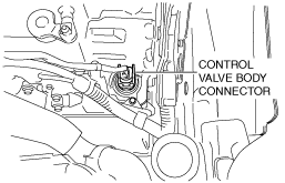
4. Disconnect the control valve body connector.
am3uuw00008326
|
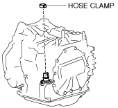
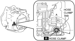
5. Remove the hose clamp.
am3uuw00008327
|
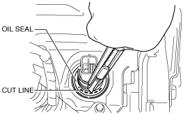
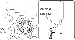
6. Cut the oil seal using a utility knife as shown in the following illustration.
am3uuw00008328
|
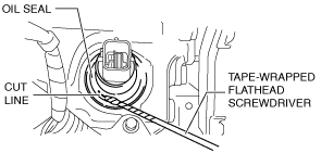
7. Using a tape-wrapped flathead screwdriver, remove the oil seal from the transaxle case.
am3uuw00009191
|
am3uuw00009192
|
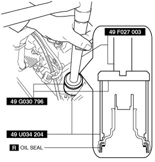
8. Temporarily install the oil seal (control valve body) by hand.
9. Using the SSTs and a hammer, install the oil seal (control valve body) so that it is not tilted and there is no height difference between the transaxle case surface and the end surface of the oil seal.
ac5uuw00000214
|
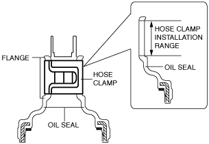
10. Install a new hose clamp to the position shown in the figure.
ac5uuw00002275
|
ac5uuw00006524
|
11. Connect the control valve body connector.
am3uuw00008326
|
12. Install the following parts as a single unit. (See INTAKE-AIR SYSTEM REMOVAL/INSTALLATION [SKYACTIV-G 2.0, SKYACTIV-G 2.5 (WITHOUT CYLINDER DEACTIVATION)].) (See INTAKE-AIR SYSTEM REMOVAL/INSTALLATION [SKYACTIV-G 2.5 (WITH CYLINDER DEACTIVATION)].)
13. Install the plug hole plate. (See PLUG HOLE PLATE REMOVAL/INSTALLATION [SKYACTIV-G 2.0, SKYACTIV-G 2.5 (WITHOUT CYLINDER DEACTIVATION)].) (See PLUG HOLE PLATE REMOVAL/INSTALLATION [SKYACTIV-G 2.5 (WITH CYLINDER DEACTIVATION)].)
14. Connect the negative battery terminal. (See NEGATIVE BATTERY TERMINAL DISCONNECTION/CONNECTION.)