 |
am6xuw00010691
INTAKE-AIR SYSTEM REMOVAL/INSTALLATION [SKYACTIV-G 2.0, SKYACTIV-G 2.5 (WITHOUT CYLINDER DEACTIVATION)]
id0113q8801900
1. Disconnect the negative battery terminal. (See NEGATIVE BATTERY TERMINAL DISCONNECTION/CONNECTION.)
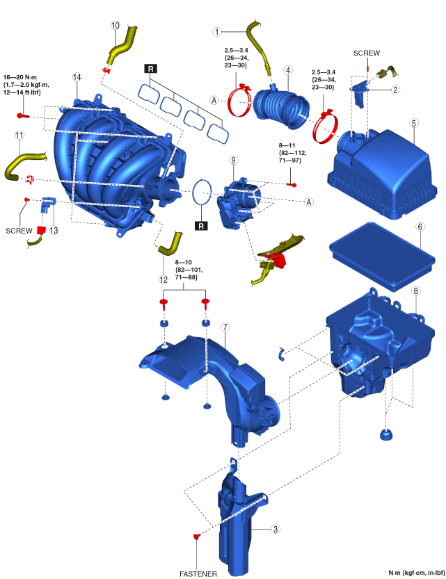
2. Remove in the order indicated in the table.
3. Install in the reverse order of removal.
am6xuw00010691
|
|
1
|
Ventilation hose
|
|
2
|
MAF sensor/IAT sensor No.1
|
|
3
|
Resonance chamber
|
|
4
|
Air hose
(See Air Hose Installation Note.)
|
|
5
|
Air cleaner cover
|
|
6
|
Air cleaner element
|
|
7
|
Fresh-air duct
(See Fresh-air Duct Removal Note.)
|
|
8
|
Air cleaner case
|
|
9
|
Throttle body
|
|
10
|
Vacuum hose
|
|
11
|
Evaporative hose
|
|
12
|
PCV hose
|
|
13
|
MAP sensor/IAT sensor No.2
|
|
14
|
Intake manifold
|
Resonance Chamber Removal Note
1. Remove the following parts as a single unit:
2. Remove the resonance chamber.
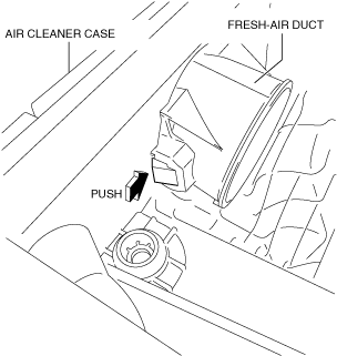
Fresh-air Duct Removal Note
1. Pull out the fresh-air duct while pressing the tab shown in the figure.
am6xuw00006500
|
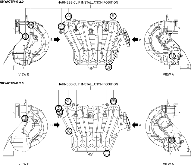
Intake Manifold Removal Note
1. Remove the MAP sensor/IAT sensor No.2. (See MANIFOLD ABSOLUTE PRESSURE (MAP) SENSOR/INTAKE AIR TEMPERATURE (IAT) SENSOR NO.2 REMOVAL/INSTALLATION [SKYACTIV-G 2.0, SKYACTIV-G 2.5 (WITHOUT CYLINDER DEACTIVATION)].)
2. Disconnect the harness clip from the intake manifold as shown in the figure.
ac5uuw00009258
|
3. Remove the intake manifold.
Intake Manifold Installation Note
1. Install the intake manifold.
2. Connect the harness clip to the intake manifold as shown in the figure.
ac5uuw00009258
|
3. Install the MAP sensor/IAT sensor No.2. (See MANIFOLD ABSOLUTE PRESSURE (MAP) SENSOR/INTAKE AIR TEMPERATURE (IAT) SENSOR NO.2 REMOVAL/INSTALLATION [SKYACTIV-G 2.0, SKYACTIV-G 2.5 (WITHOUT CYLINDER DEACTIVATION)].)
Evaporative Hose Installation Note
1. Install the evaporative hose as shown in the figure.
am6xuw00006501
|
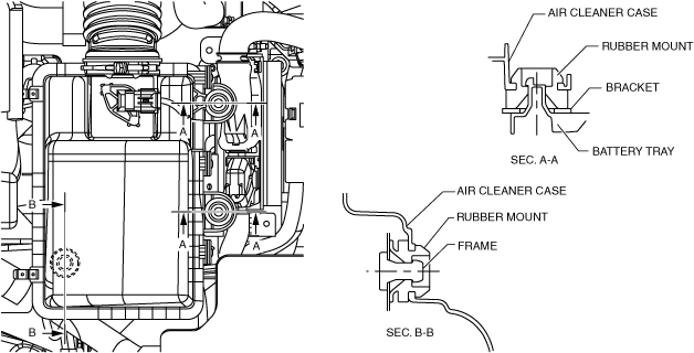
Air Cleaner Case Installation Note
1. Install the air cleaner case as shown in the figure.
am6xuw00006503
|
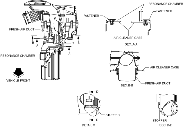
Fresh-air Duct Installation Note
1. Install the fresh-air duct as shown in the figure.
am6xuw00005242
|
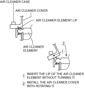
Air Cleaner Cover Installation Note
1. Install the air cleaner cover as shown in the figure.
ac5wzw00005692
|
2. Secure the air cleaner cover and the air cleaner case with the clip.
ac5wzw00010720
|
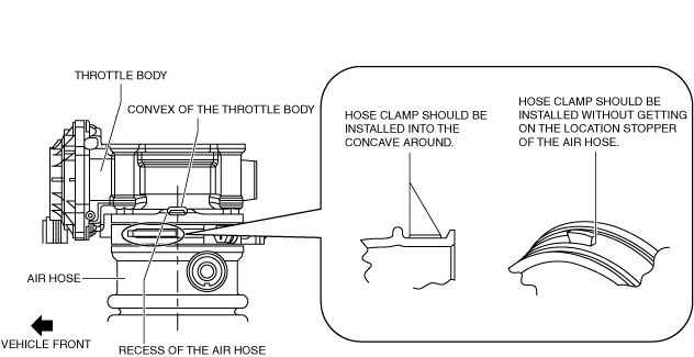
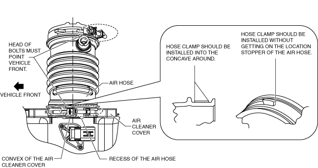
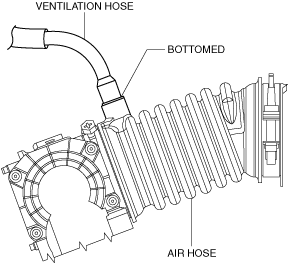
Air Hose Installation Note
1. Install the air hose as shown in the figure.
Throttle body side
am6xuw00007939
|
Air cleaner side
am6xuw00007940
|
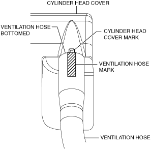
Ventilation Hose Installation Note
1. Install the ventilation hose as shown in the figure.
Cylinder head cover side
am6xuw00006506
|
Air hose side
am6xuw00006507
|