 |
am6xuw00009751
STEERING GEAR AND LINKAGE ASSEMBLY
id061300802100
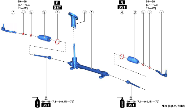
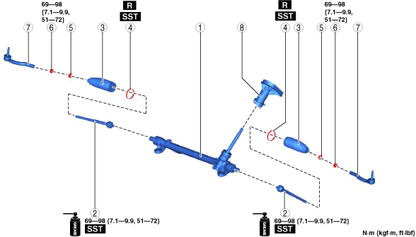
1. Assemble in the order shown in the figure.
2. Install the steering gear and linkage to the front crossmember. (See STEERING GEAR AND LINKAGE REMOVAL/INSTALLATION.)
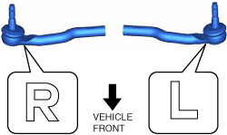
L.H.D.
am6xuw00009751
|
R.H.D.
am6zzw00017053
|
|
1
|
Steering gear
|
|
2
|
Tie Rod
(See Tie Rod Assembly Note.)
|
|
3
|
Boot
|
|
4
|
Boot band
(See Boot Band Assembly Note.)
|
|
5
|
Boot clamp
|
|
6
|
Locknut
|
|
7
|
Tie-rod end
(See Tie-rod End Assembly Note.)
|
|
8
|
Dust cover
|
Tie Rod Assembly Note
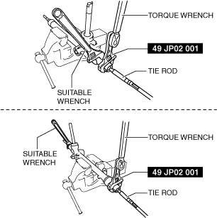
1. Install the SST to the torque wrench as shown in the figure, set it on the tie rod, and measure dimensions A and L shown in the figure.
adejjw00015170
|
2. Tighten the tie rod after calculating the tightening torque using the following formula.
am6xuw00009752
|
Boot Band Assembly Note
1. Assemble the boot band to the boot.
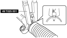
2. Crimp the boot band using the SST.
ac5jjw00002709
|
3. Verify that the crimping clearance A is within the specification.
4. Rotate the by hand and verify that it is securely installed to the boot band.
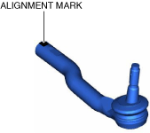
Tie-rod End Assembly Note
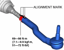
1. Align the alignment marks made before removal and assemble the tie-rod end to the tie rod.
am6xuw00009753
|
am6xuw00009754
|
am6xuw00009739
|
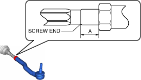
2. Adjust dimension A shown in the figure to the standard, then assemble the tie-rod end.
am6xuw00009755
|