 |
am6xuw00010529
STEERING GEAR AND LINKAGE REMOVAL/INSTALLATION
id061300801700
1. Remove the wheels and tires. (See WHEEL AND TIRE REMOVAL/INSTALLATION.)
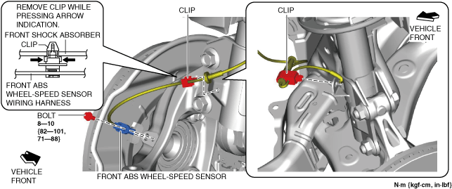
2. Disconnect the front ABS wheel-speed sensor wiring harness installed to the steering knuckle and set it aside.
am6xuw00010529
|
3. Remove the following parts:
4. Detach the tie-rod end from the steering knuckle. (See TIE-ROD END REPLACEMENT.)
5. Disconnect the front lower arm ball joint from the steering knuckle. (See FRONT LOWER ARM REMOVAL/INSTALLATION.)
6. Remove the joint cover. (See STEERING WHEEL AND COLUMN REMOVAL/INSTALLATION.)
7. Disconnect the intermediate shaft from the steering gear and linkage. (See STEERING WHEEL AND COLUMN REMOVAL/INSTALLATION.)
8. Remove the front crossmember component. (See FRONT CROSSMEMBER REMOVAL/INSTALLATION.)
9. Remove in the order indicated in the table.
10. Install in the reverse order of removal.
11. After installation, inspect the front wheel alignment and adjust it if necessary. (See FRONT WHEEL ALIGNMENT.)
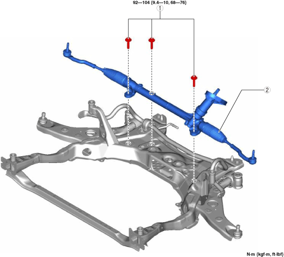
L.H.D.
am6xuw00009745
|
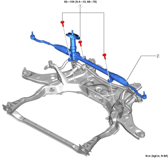
R.H.D.
am6zzw00017050
|
|
1
|
Steering gear and linkage installation bolt
|
|
2
|
Steering gear and linkage
|
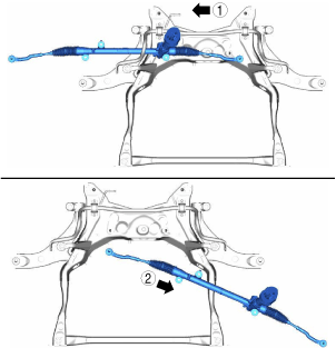
Steering Gear and Linkage Removal Note
1. Remove the steering gear and linkage installation bolts, move the steering gear and linkage in the direction and order of the arrows shown in the figure, and then remove it.
L.H.D.
am6xuw00009746
|
R.H.D.
am6zzw00017051
|