|
1
|
INSPECT FRONT COMBINATION LIGHT (RH) CONNECTOR CONDITION
• Switch the ignition off.
• Disconnect the negative battery terminal.
• Disconnect the front combination light (RH) connector.
• Inspect the connector engagement and connection condition and inspect the terminals for damage, deformation, corrosion, or disconnection.
• Is the connector normal?
|
Yes
|
Go to the next step.
|
|
No
|
Repair or replace the connector, then go to Step 7.
|
|
2
|
INSPECT AFS CONTROL MODULE CONNECTOR CONDITION
• Disconnect the AFS control module connector.
• Inspect the connector engagement and connection condition and inspect the terminals for damage, deformation, corrosion, or disconnection.
• Is the connector normal?
|
Yes
|
Go to the next step.
|
|
No
|
Repair or replace the connector, then go to Step 7.
|
|
3
|
INSPECT SWIVEL ACTUATOR (RH) CIRCUIT FOR SHORT TO GROUND
• Verify that the front combination light (RH) and AFS control module connectors are disconnected.
• Inspect for continuity between the following terminals (vehicle wiring harness side) and body ground.
-
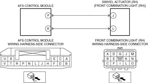
― Front combination light (RH) terminal J
― Front combination light (RH) terminal L
• Is there continuity?
|
Yes
|
Refer to the wiring diagram and verify whether or not there is a common connector between the following terminals:
• AFS control module terminal P and front combination light (RH) terminal J
• AFS control module terminal R and front combination light (RH) terminal L
If there is a common connector:
• Determine the malfunctioning part by inspecting the common connector and the terminal for corrosion, damage, or pin disconnection, and the common wiring harness for a short to ground.
• Repair or replace the malfunctioning part.
If there is no common connector:
• Repair or replace the wiring harness which has a short to ground.
Go to Step 7.
|
|
No
|
Go to the next step.
|
|
4
|
INSPECT SWIVEL ACTUATOR (RH) CIRCUIT FOR SHORT TO POWER SUPPLY
• Verify that the front combination light (RH) and AFS control module connectors are disconnected.
• Disconnect the front combination light (LH) connector.
-
Note
-
• The inspection cannot be performed correctly if the voltage is measured without disconnecting the front combination light (LH) connector because power is supplied to the front combination light (RH) via the front combination light (LH).
• Connect the negative battery terminal.
• Switch the ignition ON (engine off or on).
• Measure the voltage at the following terminals (vehicle wiring harness side).
-
― Front combination light (RH) terminal J
― Front combination light (RH) terminal L
• Is the voltage 0 V?
|
Yes
|
Go to the next step.
|
|
No
|
Refer to the wiring diagram and verify whether or not there is a common connector between the following terminals:
• AFS control module terminal P and front combination light (RH) terminal J
• AFS control module terminal R and front combination light (RH) terminal L
If there is a common connector:
• Determine the malfunctioning part by inspecting the common connector and the terminal for corrosion, damage, or pin disconnection, and the common wiring harness for a short to power supply.
• Repair or replace the malfunctioning part.
If there is no common connector:
• Repair or replace the wiring harness which has a short to power supply.
Go to Step 7.
|
|
5
|
INSPECT SWIVEL ACTUATOR (RH) CIRCUIT FOR OPEN CIRCUIT
• Verify that the front combination light (RH) and AFS control module connectors are disconnected.
• Switch the ignition off.
• Disconnect the negative battery terminal.
• Inspect the wiring harness between the following terminals (vehicle wiring harness side) for continuity.
-
― AFS control module terminal P and front combination light (RH) terminal J
― AFS control module terminal R and front combination light (RH) terminal L
• Is there continuity?
|
Yes
|
Go to the next step.
|
|
No
|
Refer to the wiring diagram and verify whether or not there is a common connector between the following terminals:
• AFS control module terminal P and front combination light (RH) terminal J
• AFS control module terminal R and front combination light (RH) terminal L
If there is a common connector:
• Determine the malfunctioning part by inspecting the common connector and the terminal for corrosion, damage, or pin disconnection, and the common wiring harness for an open circuit.
• Repair or replace the malfunctioning part.
If there is no common connector:
• Repair or replace the wiring harness which has an open circuit.
Go to Step 7.
|
|
6
|
PERFORM DTC INSPECTION AND VERIFY IF MALFUNCTIONING PART IS SWIVEL ACTUATOR (RH)
• Reconnect all the disconnected connectors.
• Reconnect the disconnected negative battery terminal.
• Clear the AFS control module DTCs using the M-MDS.
• Switch the ignition ON (engine off or on) and wait for 5 s or more.
• Perform the DTC inspection for the AFS control module using the M-MDS.
• Is the same Pending DTC present?
|
Yes
|
Replace the front combination light (RH), then go to the next step.
|
|
No
|
Go to Step 8.
|
|
7
|
VERIFY THAT REPAIRS HAVE BEEN COMPLETED
• Reconnect all the disconnected connectors.
• Reconnect the disconnected negative battery terminal.
• Clear the AFS control module DTCs using the M-MDS.
• Switch the ignition ON (engine off or on) and wait for 5 s or more.
• Perform the DTC inspection for the AFS control module using the M-MDS.
• Is the same Pending DTC present?
|
Yes
|
Repeat the inspection from Step 1.
• If the malfunction recurs, replace the AFS control module, then go to the next step.
|
|
No
|
Go to the next step.
|
|
8
|
VERIFY IF OTHER DTCs DISPLAYED
• Are any other DTCs displayed?
|
Yes
|
Repair the malfunctioning part according to the applicable DTC troubleshooting.
|
|
No
|
DTC troubleshooting completed.
|