1. Disconnect the negative battery cable.
2. Remove the plug hole plate. (See PLUG HOLE PLATE REMOVAL/INSTALLATION [L3].)
3. Remove the high-tension lead. (See HIGH-TENSION LEAD REMOVAL/INSTALLATION [LF, L3].)
4. Remove the oil control valve (OCV) connector.
5. Remove the ventilation hose.
6. Remove the cylinder head cover.
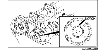
7. Confirm that the groove on the rotor and the notch on the cover of the variable valve timing actuator are aligned and fitted.
8. Install the cylinder head cover. (See Cylinder Head Cover Installation Note.)
9. Install the ventilation hose.
10. Install the oil control valve (OCV) connector.
11. Install the high-tension lead. (See HIGH-TENSION LEAD REMOVAL/INSTALLATION [LF, L3].)
12. Install the plug hole plate. (See PLUG HOLE PLATE REMOVAL/INSTALLATION [L3].)