KNOCK SENSOR INSPECTION [LF, L3]
id0140008028a6
-
Note
-
• Perform the following test only when directed.
Resistance Inspection
1. Turn the ignition switch to LOCK position.
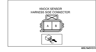
2. Disconnect the knock sensor connector.
3. Measure the resistance between the knock sensor terminals A and B using an ohmmeter.
-
• If not as specified, replace the knock sensor.
-
• If the knock sensor is okay, but PID value is out of specification, perform the "Circuit Open/Short Inspection".
-
Specification
-
Approx. 4.87 megohms
Circuit Open/Short Inspection
1. Disconnect the PCM connector. (See PCM REMOVAL/INSTALLATION [LF, L3].)
2. Inspect the following wiring harnesses for open or short. (Continuity check)
Open circuit
-
• If there is no continuity, the circuit is open. Repair or replace the harness.
-
- Knock sensor terminal A (harness-side) and PCM terminal 2S (harness-side)
-
- Knock sensor terminal B (harness-side) and PCM terminal 2P (harness-side)
Short circuit
-
• If there is continuity, the circuit is shorted. Repair or replace the harness.
-
- Knock sensor terminal A (harness-side) and power supply
-
- Knock sensor terminal A (harness-side) and body GND
-
- Knock sensor terminal B (harness-side) and power supply
-
- Knock sensor terminal B (harness-side) and body GND