1. Disassemble in the order indicated in the table.
2. Assemble in the reverse order of disassembly.
|
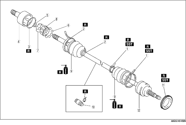
1
|
Boot band (wheel side)
|
|
2
|
Boot band (transaxle side)
|
|
3
|
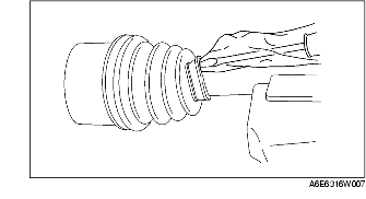
Clip
(See Clip Disassembly Note)
|
|
4
|
Outer ring
|
|
5
|
Snap ring
|
|
6
|
Balls
|
|
7
|
Inner Ring
|
|
8
|
Cage
|
|
9
|
Boot
(See Boot Assembly Note)
|
|
10
|
Dynamic damper
|
|
11
|
ABS sensor rotor
|
|
12
|
Shaft and ball joint component
|
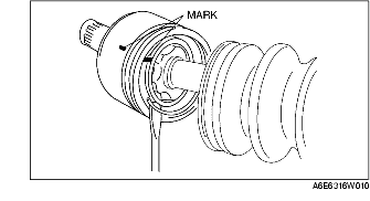
1. Mark the drive shaft and outer ring for proper assembly.
2. Remove the clip.
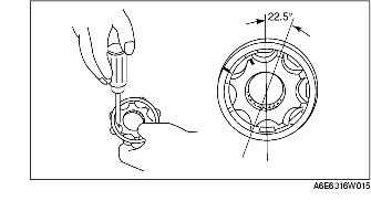
1. Mark the inner ring and cage.
2. Remove the snap ring using snap-ring pliers.
3. Turn the cage approximately 22.5 degree and pull the cage and balls away from the inner ring.
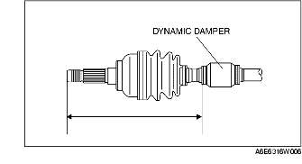
1. Install the dynamic damper as shown in the figure.
2. Install the new boot band onto the dynamic damper.
1. Fill the boot (wheel side) with the specified grease.
2. With the splines of the shaft still wrapped in tape from disassembly, install the boot.
3. Remove the tape.
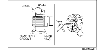
1. Align the marks and install the balls and cage to the inner ring in the direction shown in the figure.
2. Install a new snap ring.
1. Fill the outer ring and boot (transaxle side) with the specified grease.
2. Align the marks, and install the outer ring on to the shaft.
3. Install a new clip.
4. Install the boot.
5. Set the drive shaft to the standard length.
6. Release any trapped air from the boots by carefully lifting up the small end of each boot with a cloth wrapped screwdriver.
7. Verify that the drive shaft length is within the specification.