|
Terminal
|
Signal
|
Connected to
|
Test condition
|
Voltage (V)
|
Action
|
|
A
B
|
RR wheel-speed
|
RR wheel-speed sensor
|
Vehicle is stopped
|
0 (AC)
|
• Inspect related harnesses
• Inspect ABS wheel-speed sensor
|
|
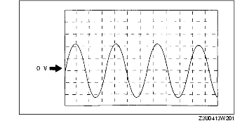
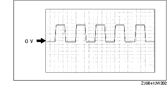
• Inspect by using the wave profile.
|
|
C
F
|
LR wheel-speed
|
LR wheel-speed sensor
|
Vehicle is stopped
|
0 (AC)
|
|
• Inspect by using the wave profile.
|
|
G
D
|
RF wheel-speed
|
RF wheel-speed sensor
|
Vehicle is stopped
|
0 (AC)
|
|
• Inspect by using the wave profile.
|
|
I
E
|
LF wheel-speed
|
LF wheel-speed sensor
|
Vehicle is stopped
|
0 (AC)
|
|
• Inspect by using the wave profile.
|
|
H
|
-
|
-
|
-
|
-
|
-
|
|
K
|
-
|
-
|
-
|
-
|
-
|
|
L
|
-
|
-
|
-
|
-
|
-
|
|
M
|
-
|
-
|
-
|
-
|
-
|
|
N
|
-
|
-
|
-
|
-
|
-
|
|
O
|
CAN-H
|
-
|
-
|
No need to check
|
-
|
|
P*1
|
TCS OFF switch
|
TCS OFF switch
|
When switch is pressed
|
Below 1.0
|
• Inspect related harnesses
• Inspect TCS OFF switch
|
|
When switch is not pressed
|
B+
|
|
Q
|
-
|
-
|
-
|
-
|
-
|
|
R
|
CAN-L
|
-
|
-
|
No need to check
|
-
|
|
S
|
-
|
-
|
-
|
-
|
-
|
|
T
|
-
|
-
|
-
|
-
|
-
|
|
U*2
|
-
|
Check connector
|
-
|
No need to check
|
-
|
|
V
|
Vehicle speed output
|
• Cruise actuator
• Audio unit
• Auto leveling control unit
• Wiper and washer switch
|
Vehicle is stopped
|
0
|
• Inspect related harnesses
• Inspect ABS wheel-speed sensor
|
|
• Inspect by using the wave profile.
|
|
W
|
-
|
-
|
-
|
-
|
-
|
|
X
|
OBD
|
KLN terminal of DLC-2
|
It cannot be determined with terminal voltage whether the condition is good or bad because advanced function diagnostic output is performed with serial communication. Inspect with service codes.
|
• Inspect related harnesses
• Inspect ABS/TCS HU/CM
|
|
Y
|
Brake switch
|
Brake switch
|
Brake pedal is depressed
|
10-14
|
• Inspect related harnesses
|
|
Brake pedal is released
|
Below 0.5
|
|
Z
|
Power supply
|
Ignition switch
|
-
|
B+
|
• Inspect related harnesses
|
|
AA
|
Power supply (Solenoid valve)
|
Battery
|
-
|
B+
|
• Inspect related harnesses
|
|
AB
|
Power supply (ABS motor)
|
Battery
|
-
|
B+
|
|
AC
|
Ground
|
Ground
|
-
|
0
|
• Inspect related harnesses
|
|
AD
|
Ground
|
Ground
|
-
|
0
|
• Inspect related harnesses
|