 |
am6zzw00012701
VEHICLE SPEEDOMETER SENSOR (VSS) INSPECTION [WITHOUT ABS]
id0517a12650b7
Visual Inspection
1. Remove the VSS. (See VEHICLE SPEEDOMETER SENSOR (VSS) REMOVAL/INSTALLATION [WITHOUT ABS].)
2. Make sure that the sensor is free of any metallic shavings or particles.
3. Install the VSS. (See VEHICLE SPEEDOMETER SENSOR (VSS) REMOVAL/INSTALLATION [WITHOUT ABS].)
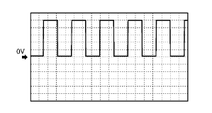
Wave profile Inspection
1. Remove the PCM. (See PCM REMOVAL/INSTALLATION [LF, L3].)
2. Connect WDS or equivalent to DLC connector.
3. Connect oscilloscope test leads to the following PCM connector terminals.
4. Start the engine.
5. Monitor VSS PID.
6. Inspect wave profile.
am6zzw00012701
|
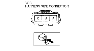
Power Supply Voltage Inspection
1. Disconnect the VSS connector.
2. Turn the ignition switch to ON.
3. Measure voltage at VSS connector terminal A (wiring harness side).
am6zzw00012702
|
Open Circuit Inspection
1. Inspect the following circuit for open.
Short Circuit Inspection
1. Inspect the following circuit for short.
am6zzw00012702
|
Sensor Rotor Inspection
1. Remove the VSS. (See VEHICLE SPEEDOMETER SENSOR (VSS) REMOVAL/INSTALLATION [WITHOUT ABS].)
2. Shift the selector lever to N position.
3. Inspect sensor rotor surface via VSS installation hole while rotating the front tire manually.