DIAGNOSTIC TROUBLE CODE NUMBER INSPECTION
id070200802000
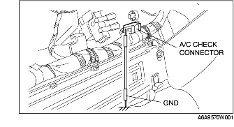
1. Remove the glove compartment.
2. Short the A/C check connector to the GND terminal using a jumper wire.
3. Shine a 60 W incandescent light from a height of approximately 100 mm {3.9 in} onto the solar radiation sensor.
-
Note
-
• When incandescent light does not shine on the solar radiation sensor, the climate control unit determines a malfunction and indicates a diagnostic trouble code "02".
4. Turn the ignition switch to ON position.
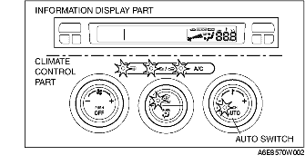
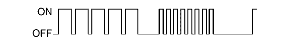
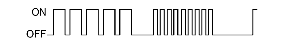
5. Read DTCs from the flashing of the DEFROSTER switch indicator light on the climate control unit. Carry out DTC inspection. (present and past failure indication modes)
-
• When the system is normal, the DEFROSTER switch indicator light does not flash.
-
• If any of the diagnostic trouble codes are indicated, carry out troubleshooting according to the code.
6. After completion of repairs, erase all diagnostic trouble code(s) from memory. (See Erasing Past Failure Memory.)
7. Remove the jumper wire.
Present Failure Indication Mode
• The on-board diagnostic function display the present failure indication mode directly after start up. In present failure indication mode, present failures in the control system circuits (open, short circuits) are detected, and the flashing of the DEFROSTER switch indicator light on the climate control unit indicates the DTCs.
-
- If a diagnostic trouble code is indicated, refer to the following diagnostic trouble code table and inspect the appropriate system.
Past Failure Indication Mode
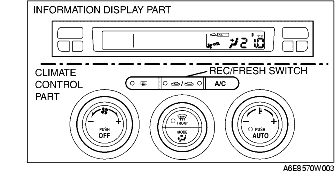
• While in present failure indication mode, press the A/C switch to change to the past failure indication mode. In past failure indication mode, past failures (intermittent problems) in the input sensor circuits (open, short circuits) are shorted, and the flashing of the DEFROSTER switch indicator light on the climate control unit indicates the DTCs.
-
- If a diagnostic trouble code is indicated, refer to the following diagnostic trouble code table and inspect the appropriate system. (Disconnections and short circuits are memorized in the same system even if either occurs only once.)
-
- If the A/C switch is pressed again while in past failure indication mode, the on-board diagnostic function will return to present failure indication mode.
Erasing Past Failure Memory
• When DTCs are displayed in the past failure indication mode, they remain in the memory after the failed systems are corrected. Consequently, the next time the past failure indication mode is used, the same past failure DTCs will be indicated by the flashing of the DEFROSTER switch indicator light on the climate control unit. Therefore, erase the past failure memory after correcting all failed systems. To erase the past failure memory, press the AUTO switch and REC/FRESH switch on the climate control unit at the same time while in past failure indication mode. If erased, the DEFROSTER switch indicator light flashes once.
DTC Table
|
No.
|
Indicator pattern
|
Diagnosed circuit
|
|
02
|

|
Solar radiation sensor (present)
|
|
06
|

|
Cabin temperature sensor (present)
|
|
07
|

|
Cabin temperature sensor (past)
|
|
10
|

|
Evaporator temperature sensor (present)
|
|
11
|

|
Evaporator temperature sensor (past)
|
|
12
|

|
Ambient temperature sensor (present)
|
|
13
|

|
Ambient temperature sensor (past)
|
|
14
|

|
Water temperature sensor (present)
|
|
15
|

|
Water temperature sensor (past)
|
|
18
|

|
Air mix actuator [potentiometer] (present)
|
|
19
|

|
Air mix actuator [potentiometer] (past)
|
|
21
|

|
Airflow mode actuator [potentiometer] (present)
|
|
22
|

|
Airflow mode actuator [potentiometer] (past)
|
|
58
|
|
Air mix actuator [motor lock] (past)
|
|
59
|
|
Airflow mode actuator [motor lock] (past)
|
Output Device Operation Check Mode
Inspection
1. Warm up the engine.
2. Turn the ignition switch to LOCK position.
3. Start up the on-board diagnostic function (present failure indication mode).
4. Press the AUTO switch.
5. Verify that all the indicator lights of the climate control unit and center panel (climate control part) illuminate for 4 seconds.
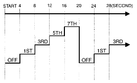
6. Verify the operation of the each output device when changing steps by pressing the REC/FRESH switch, and referring to the output device operation check chart.
-
• If not as specified, inspect the malfunctioning system.
-
Note
-
• If the AUTO switch is pressed again, the on-board diagnostic function will return to present failure indication mode.
7. Turn the ignition switch to LOCK position to end the on-board diagnostic function.
Output device operation check table
|
Step
|
Operating device
|
Operating conditions
|
Moni tor*
|
Other device conditions
|
|
1
|
Blower motor speed
|
|
1
|
• Air mix actuator operation
-
- 50%
• Airflow mode actuator operation
-
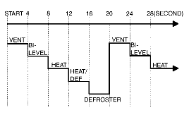
- VENT
• Air intake actuator operation
-
- FRESH
• A/C compressor operation
-
- ON
|
|
2
|
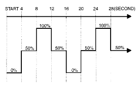
Air mix actuator operation
|
|
21.0
|
• Blower motor speed
-
- 3rd
• Airflow mode actuator operation
-
- VENT
• Air intake actuator operation
-
- FRESH
• A/C compressor operation
-
- ON
|
|
20.5
|
|
20.0
|
|
3
|
Airflow mode actuator operation
|
|
3
|
• Blower motor speed
-
- 3rd
• Air mix actuator operation
-
- 50%
• Air intake actuator operation
-
- FRESH
• A/C compressor operation
-
- ON
|
|
4
|
Air intake actuator operation
|

|
4
|
• Blower motor speed
-
- 3rd
• Air mix actuator operation
-
- 0%
• Airflow mode actuator operation
-
- VENT
|
|
A/C compressor operation
|
|
-
* :
Shown on the information display according to step.