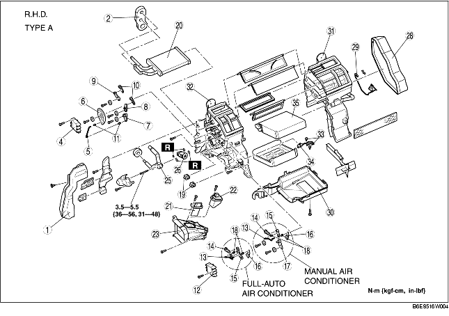
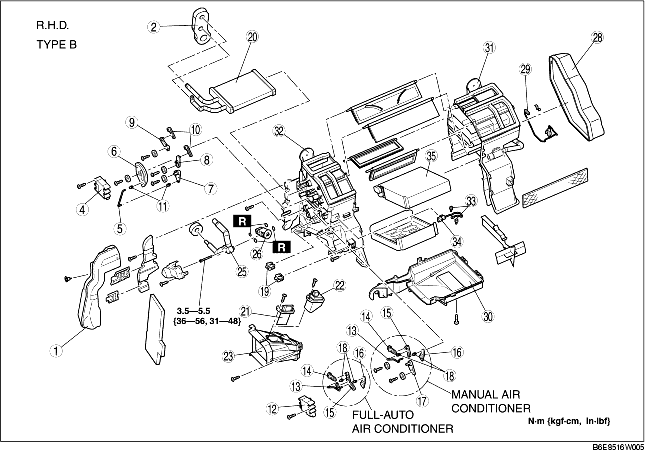
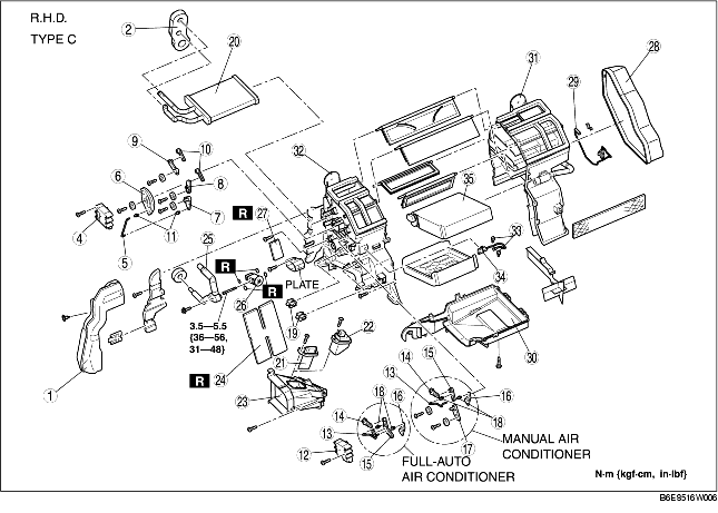
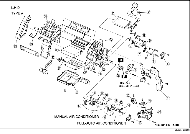
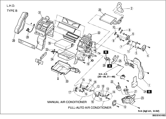
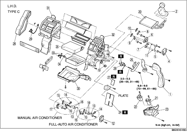
1. Disassemble in the order indicated in the table.
2. Assemble in the reverse order of disassembly.
|
1
|
Duct (1)
|
|
2
|
Polyurethane protector (1)
|
|
3
|
Polyurethane protector (2) (R.H.D., L.H.D. type C)
|
|
4
|
Airflow mode actuator (full-auto air conditioner)
|
|
5
|
Airflow mode rod (manual air conditioner)
|
|
6
|
Airflow mode main link
|
|
7
|
Airflow mode sub link (1) (manual air conditioner)
|
|
8
|
Airflow mode sub link (2)
|
|
9
|
Airflow mode sub link (3)
|
|
10
|
Airflow mode crank
|
|
11
|
Airflow mode rod holder (manual air conditioner)
|
|
12
|
Air mix actuator (full-auto air conditioner)
|
|
13
|
Air mix rod
|
|
14
|
Air mix crank (1)
|
|
15
|
Air mix link (1)
|
|
16
|
Air mix crank (2)
|
|
17
|
Air mix link (2) (manual air conditioner)
|
|
18
|
Air mix rod holder
|
|
19
|
Wire clamp (manual air conditioner)
|
|
20
|
Heater core
|
|
21
|
Resistor (manual air conditioner)
|
|
22
|
Power MOS FET (full-auto air conditioner)
|
|
23
|
Duct (2)
|
|
24
|
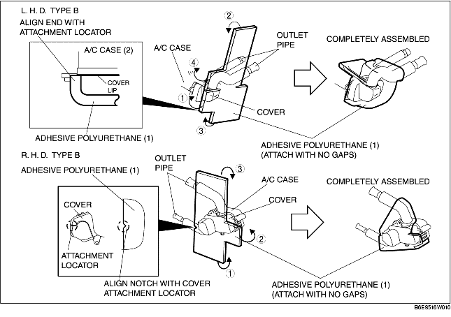
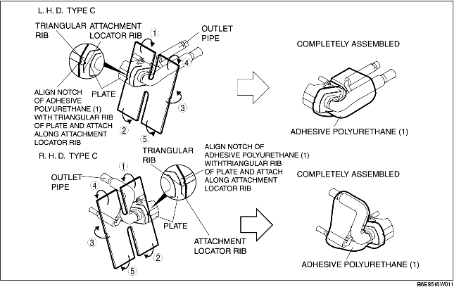
Adhesive polyurethane (1)
|
|
25
|
Outlet pipe
|
|
26
|
Expansion valve
|
|
27
|
Adhesive polyurethane (2)
|
|
28
|
Duct (3)
|
|
29
|
Water temperature sensor (full-auto air conditioner)
|
|
30
|
A/C case (3)
(See A/C Case Assembly Note)
|
|
31
|
A/C case (1)
(See A/C Case Assembly Note)
|
|
32
|
A/C case (2)
(See A/C Case Assembly Note)
|
|
33
|
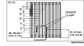
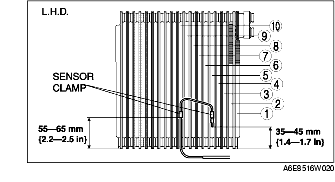
Sensor clamp
|
|
34
|
Evaporator temperature sensor
|
|
35
|
Evaporator
|
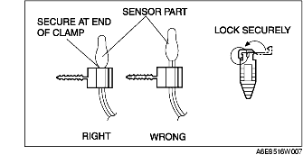
1. Assemble the evaporator temperature sensor as shown in the figure.
1. Attach the sensor clamp as shown in the figure.
1. Before assembling the A/C case, apply sealant (one-component, non-solvent, non-alcohol type) to the groove along the joint where A/C case (1) and A/C case (3) are joined. Make sure to apply sealant completely around the whole periphery of the joint, and that there are no gaps.
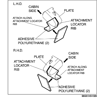
1. Attach the adhesive polyurethane (2) as shown in the figure.
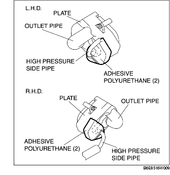
2. After assembling the outlet pipe as shown in the figure, attach the adhesive polyurethane (2) so that it adheres around the hipressure side of the outlet pipe.
1. Attach the adhesive polyurethane (2) as shown in the figure.