Diagnostic procedure
|
STEP
|
INSPECTION
|
ACTION
|
|
|---|---|---|---|
|
1
|
INSPECT DRIVER-SIDE AIR BAG MODULE (INFLATOR NO.1)
• Check following PID/DATA monitor, using SST (WDS or equivalent).
(See PID/DATA MONITOR TABLE)
• Is resistant value of driver-side air bag module normal?
|
Yes
|
Present malfunction diagnosis:
• Replace SAS unit.
Past malfunction diagnosis:
• Troubleshooting completed.
|
|
No
|
Go to next step.
|
||
|
2
|
INSPECT DRIVER-SIDE AIR BAG MODULE CONNECTOR (CLOCK SPRING)
• Turn ignition switch to LOCK position.
• Disconnect negative battery cable and wait for more than 1 minute.
• Remove driver-side air bag module.
• Is there cracking or chipping in driver-side air bag module connector?
|
Yes
|
Replace wiring harness.
|
|
No
|
Go to next step.
|
||
|
3
|
VERIFY WHETHER MALFUNCTION IS IN DRIVER-SIDE AIR BAG MODULE (INFLATOR NO.1) OR RELATED WIRING HARNESS
• Connect leads of SST (Fuel and thermometer checker) or apply 2 ohm resistor to driver-side air bag module (inflator No.1) connector terminal 3A and 3B, and driver-side air bag module (inflator No.2) connector terminal 4A and 4B.
• Set resistance of SST (Fuel and thermometer checker) to 2 ohm.
• Connect negative battery cable.
• Turn ignition switch to ON position.
• Check following PID/DATA monitor, using SST (WDS or equivalent).
(See PID/DATA MONITOR TABLE)
• Is related wiring harness normal?
|
Yes
|
Replace driver-side air bag module.
|
|
No
|
Go to next step.
|
||
|
4
|
INSPECT CLOCK SPRING
• Inspect clock spring.
(See CLOCK SPRING INSPECTION)
• Is clock spring normal?
|
Yes
|
Go to next step.
|
|
No
|
Replace clock spring.
|
||
|
5
|
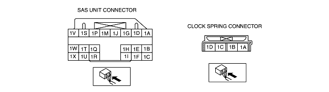
INSPECT WIRING HARNESS BETWEEN CLOCK SPRING AND SAS UNIT
• Turn ignition switch to LOCK position.
• Disconnect negative battery cable and wait for more than 1 minute.
• Remove column cover.
• Disconnect clock spring connector.
• Remove glove compartment.
• Disconnect passenger-side air bag module connector.
• Disconnect driver and passenger-side side air bag module connectors. (Vehicle with side air bag)
• Disconnect driver and passenger-side curtain air bag module connectors. (Vehicle with curtain air bag)
• Remove B-pillar lower trim. (Vehicle with pre-tensioner seat belt)
• Disconnect driver and passenger-side pre-tensioner seat belt connectors. (Vehicle with pre-tensioner seat belt)
• Turn up floor covering.
• Disconnect all SAS unit connectors.
• Inspect following wiring harnesses between SAS unit and clock spring terminals for short to ground, short to power supply, and open circuit:
• Is wiring harness okay?
|
Yes
|
Present malfunction diagnosis:
• Replace SAS unit.
Past malfunction diagnosis:
• Troubleshooting completed.
|
|
No
|
Replace wiring harnesses.
|
||