|
STEP
|
INSPECTION
|
ACTION
|
|
1
|
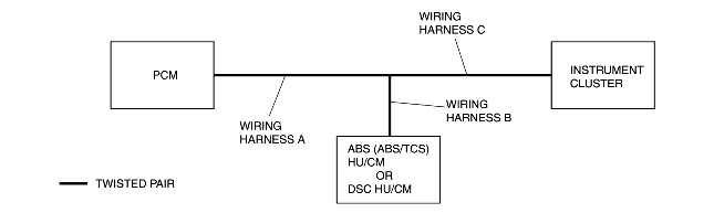
DETERMINING THE LOCATION OF A MALFUNCTION
• Determine the malfunctioning part of the CAN system.
• Is the malfunctioning part the wiring harness C or the instrument cluster?
|
Yes
|
Go to Step 4.
|
|
No
|
Go to next step.
|
|
2
|
DETERMINING THE LOCATION OF A MALFUNCTION
• Is the malfunctioning part the wiring harness B or the ABS (ABS/TCS) HU/CM? (with ABS (ABS/TCS))
• Is the malfunctioning part the wiring harness B or the DSC HU/CM? (with DSC)
|
Yes
|
Go to Step 8.
|
|
No
|
Go to next step.
|
|
3
|
DETERMINING THE LOCATION OF A MALFUNCTION
• Is the malfunctioning part the wiring harness A or the PCM?
|
Yes
|
Go to Step 12.
|
|
No
|
Troubleshooting completed.
|
|
4
|
INSPECT INSTRUMENT CLUSTER CONNECTOR
• Disconnect negative battery cable.
• Disconnect instrument cluster connector.
• Is poor connection detection bars of instrument cluster connector okay?
|
Yes
|
Go to next step.
|
|
No
|
Replace wiring harness.
|
|
5
|
• Is vehicle equipped with DSC?
|
Yes
|
Go to next step.
|
|
No
|
Go to Step 7.
|
|
6
|
INSPECT WIRING HARNESS BETWEEN DSC HU/CM AND INSTRUMENT CLUSTER
• Disconnect DSC HU/CM connector.
• Inspect following wiring harness between DSC HU/CM and instrument cluster terminals for short to ground, short power supply, and open circuit:
-
- AF-2W (CAN_L)
-
- AG-2X (CAN_H)
• Is wiring harness okay?
|
Yes
|
Replace instrument cluster, then go to Step 16.
|
|
No
|
Replace wiring harness.
|
|
7
|
INSPECT WIRING HARNESS BETWEEN ABS (ABS/TCS) HU/CM AND INSTRUMENT CLUSTER
• Disconnect ABS (ABS/TCS) HU/CM connector.
• Inspect following wiring harness between ABS (ABS/TCS) HU/CM and instrument cluster terminals for short to ground, short power supply, and open circuit:
-
- R-2W (CAN_L)
-
- O-2X (CAN_H)
• Is wiring harness okay?
|
Yes
|
Replace instrument cluster, then go to Step 16.
|
|
No
|
Replace wiring harness.
|
|
8
|
INSPECT ABS (ABS/TCS) HU/CM OR DSC HU/CM CONNECTOR
• Disconnect negative battery cable.
• Disconnect ABS (ABS/TCS) HU/CM or DSC HU/CM connector.
• Is poor connection detection bars of ABS (ABS/TCS) HU/CM or DSC HU/CM connector okay?
|
Yes
|
Go to next step.
|
|
No
|
Replace wiring harness.
|
|
9
|
• Is vehicle equipped with DSC?
|
Yes
|
Go to next step.
|
|
No
|
Go to Step 11.
|
|
10
|
INSPECT WIRING HARNESS BETWEEN DSC HU/CM AND INSTRUMENT CLUSTER
• Disconnect instrument cluster connector.
• Inspect following wiring harness between DSC HU/CM and instrument cluster terminals for short to ground, short power supply, and open circuit:
-
- AF-2W (CAN_L)
-
- AG-2X (CAN_H)
• Is wiring harness okay?
|
Yes
|
Replace DSC HU/CM, then go to Step 16.
|
|
No
|
Replace wiring harness.
|
|
11
|
INSPECT WIRING HARNESS BETWEEN ABS (ABS/TCS) HU/CM AND INSTRUMENT CLUSTER
• Disconnect instrument cluster connector.
• Inspect following wiring harness between ABS (ABS/TCS) HU/CM and instrument cluster terminals for short to ground, short power supply, and open circuit:
-
- R-2W (CAN_L)
-
- O-2X (CAN_H)
• Is wiring harness okay?
|
Yes
|
Replace ABS (ABS/TCS) HU/CM, then go to Step 16.
|
|
No
|
Replace wiring harness.
|
|
12
|
INSPECT PCM CONNECTOR
• Disconnect negative battery cable.
• Disconnect PCM connector.
• Is poor connection detection bars of PCM connector okay?
|
Yes
|
Go to next step.
|
|
No
|
Replace wiring harness.
|
|
13
|
• Is vehicle equipped with DSC?
|
Yes
|
Go to next step.
|
|
No
|
Go to Step 15.
|
|
14
|
INSPECT WIRING HARNESS BETWEEN PCM AND DSC HU/CM
• Disconnect negative battery cable.
• Disconnect DSC HU/CM connector.
• Inspect following wiring harness between PCM and DSC HU/CM terminals for short to ground, short power supply, and open circuit:
-
- 2R-AF (CAN_L)
-
- 2U-AG (CAN_H)
• Is wiring harness okay?
|
Yes
|
Replace PCM, then go to Step 16.
|
|
No
|
Replace wiring harness.
|
|
15
|
INSPECT WIRING HARNESS BETWEEN PCM AND ABS (ABS/TCS) HU/CM
• Disconnect negative battery cable.
• Disconnect ABS (ABS/TCS) HU/CM connector.
• Inspect following wiring harness between PCM and ABS (ABS/TCS) HU/CM terminals for short to ground, short power supply, and open circuit:
-
- 2R-R (CAN_L)
-
- 2U-O (CAN_H)
• Is wiring harness okay?
|
Yes
|
Replace PCM, then go to next step.
|
|
No
|
Replace wiring harness.
|
|
16
|
CHECK DTC INDICATE
• Connect PCM connector.
• Connect ABS (ABS/TCS) HU/CM or DSC HU/CM connector.
• Connect instrument cluster connector.
• Clear DTC from module memory using SST (WDS or equivalent).
• Perform KOEO/KOER self-test.
• Are DTCs U0073, U1900 and/or U2516 indicated?
|
Yes
|
Repeat from Step 1.
|
|
No
|
Troubleshooting completed.
|