DTC C0031:23/C0031:27/C0034:23/C0034:27/C0037:23/C0037:27/C0037:62/C003A:23/C003A:27/C003A:62 [DYNAMIC STABILITY CONTROL (DSC)]


id0402b2860000

Note
•  When only the driving wheels are rotated while the vehicle is jacked up, DTCs C0037:23 and C003A:23 are input to the memory.

DTC
C0031:23, C0031:27
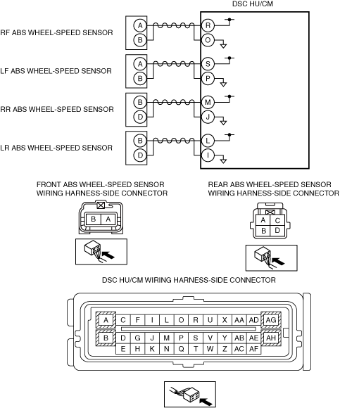
LF ABS wheel-speed sensor/ABS sensor rotor
C0034:23, C0034:27
RF ABS wheel-speed sensor/ABS sensor rotor
C0037:23, C0037:27, C0037:62
LR ABS wheel-speed sensor/ABS sensor rotor
C003A:23, C003A:27, C003A:62
RR ABS wheel-speed sensor/ABS sensor rotor
DETECTION CONDITION
•  C0031:23, C0034:23, C0037:23, C003A:23
―  The wheel-speed signal is not input from any of the four wheels when the vehicle goes from start to a speed of 10 km/h {6.2 mph} or more
―  While the vehicle is traveling, no signal in any of four wheels is detected for a continuous 30 s.
•  C0031:27, C0034:27, C0037:27, C003A:27
―  Periodic abnormality is detected in the signal wave pattern from the ABS wheel-speed sensors.
―  ABS control continues to operate for 45 s or more.
•  C0037:62, C003A:62
―  The following condition is detected 8 times continuously (One detection period is when ignition is switched from ON to off)
•  While the vehicle is traveling at a speed of 20 km/h {12 mph} or more, the wheel speed signal from the rear wheels is not input to the DSC HU/CM for a continuous 20 s.
FAIL-SAFE FUNCTION
•  Refer to “Fail-safe Function Malfunction Contents”. (See DTC TABLE [DYNAMIC STABILITY CONTROL (DSC)].)
POSSIBLE CAUSE
•  ABS wheel-speed sensor malfunction
•  ABS sensor rotor malfunction (missing ABS sensor rotor teeth due to foreign material obstruction)
•  Excessive clearance between the ABS wheel-speed sensor and sensor rotor
•  ABS wheel-speed sensor or ABS sensor rotor installation malfunction (If the ABS sensor rotor is installed at an angle, it may cause output of abnormal wave pattern at high speeds)
•  DSC HU/CM internal damage (Solenoid valve malfunction, pump motor malfunction, or pipe clogging)
•  Continuous ABS operation

Diagnostic procedure

STEP

INSPECTION

ACTION

1
INSPECT PID FOR ABS WHEEL-SPEED SENSOR OUTPUT ERROR USING M-MDS
•  Switch the ignition to off.
•  Connect the M-MDS to the DLC-2.
•  Select the following PIDs using the M-MDS:
―  WSPD_SEN_LF
―  WSPD_SEN_LR
―  WSPD_SEN_RF
―  WSPD_SEN_RR
•  Drive the vehicle.
•  Verify that the vehicle speeds detected by the four ABS wheel-speed sensors are approximately the same.
•  Are the vehicle speeds approximately the same?
Yes
Go to Step 3.
No
Go to the next step.
2
INSPECT FOR SHORT TO GROUND BETWEEN ABS WHEEL-SPEED SENSOR CONNECTORS AND GROUND
•  Disconnect the ABS wheel-speed sensor connectors.
•  Inspect for no continuity between the following ABS wheel-speed sensor connector terminals (vehicle harness-side) and body ground:
―  ABS wheel-speed sensor (RF): B—Body ground
―  ABS wheel-speed sensor (LF): B—Body ground
―  ABS wheel-speed sensor (RR): D—Body ground
―  ABS wheel-speed sensor (LR): D—Body ground
•  Is the continuity normal?
Yes
Go to the next step.
No
Refer to the wiring diagram and verify whether or not there is a common connector between the DSC HU/CM connector terminals (vehicle harness-side) and the following vehicle harness-side connector terminals of the ABS wheel-speed sensors:
•  RF ABS wheel-speed sensor(-): O—B
•  LF ABS wheel-speed sensor(-): P—B
•  RR ABS wheel-speed sensor(-): J—D
•  LR ABS wheel-speed sensor(-): I—D
If there is a common connector:
•  Determine the malfunctioning part by inspecting the common connector and the terminal for corrosion, damage, or pin disconnection, and the common wiring harness for a short to ground.
•  Repair or replace the malfunctioning part.
If there is no common connector:
•  Repair or replace the wiring harness which has a short to ground.
Go to Step 5.
3
INSPECT IF MALFUNCTION OCCURRED DUE TO IMPROPER SENSOR CLEARANCE.
•  Inspect the clearance between the ABS wheel-speed sensor and the ABS sensor rotor.
•  Is the clearance normal?
Yes
Go to the next step.
No
Replace the ABS wheel-speed sensor, then go to step 5.
4
VISUALLY INSPECT ABS SENSOR ROTOR FOR FOREIGN MATERIAL ADHERING OR IMPROPER INSTALLATION
•  Is the result normal?
Yes
Go to the next step.
No
Replace the wheel hub component, then go to next step.
5
VERIFY DTC TROUBLESHOOTING COMPLETED
•  Using the M-MDS, clear the DTC from the DSC HU/CM.
•  Start the engine and drive the vehicle at 20 km/h {12 mph} or more.
•  Gradually slow down and stop vehicle.
•  Using the M-MDS, perform the DSC HU/CM DTC inspection.
•  Is the same DTC present?
Yes
Repeat the inspection from Step1.
If the malfunction recurs, replace the DSC HU/CM, then go to the next step.
No
Go to the next step.
6
VERIFY NO DTC IS PRESENT
•  Are any DTCs present?
Yes
Go to the applicable DTC inspection.
No
DTC troubleshooting completed.