 |
am6zzw00012034
LOWER PANEL REMOVAL/INSTALLATION
id091700801100
Driver-side
1. Disconnect the negative battery cable. (See NEGATIVE BATTERY CABLE DISCONNECTION/CONNECTION [SKYACTIV-G 2.0, SKYACTIV-G 2.5].) (See NEGATIVE BATTERY CABLE DISCONNECTION/CONNECTION [SKYACTIV-G 2.0, SKYACTIV-G 2.5 (WITHOUT i-stop)].) (See NEGATIVE BATTERY CABLE DISCONNECTION/CONNECTION [SKYACTIV-D 2.2].)
2. Remove the following parts:
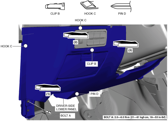
3. Remove bolt A.
am6zzw00012034
|
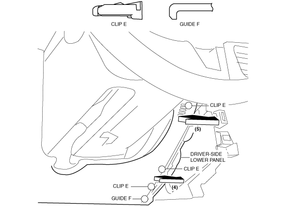
4. Pull the driver-side lower panel in the direction of the arrow in the order of (1), (2), (3) while detaching clip B, hooks C and pin D.
5. Pull the driver-side lower panel in the direction of the arrow in the order of (4), (5) and remove it while detaching clips E and guide F.
am6zzw00012035
|
6. Install in the reverse order of removal.
Passenger-side
Removal
1. Disconnect the negative battery cable. (See NEGATIVE BATTERY CABLE DISCONNECTION/CONNECTION [SKYACTIV-G 2.0, SKYACTIV-G 2.5].) (See NEGATIVE BATTERY CABLE DISCONNECTION/CONNECTION [SKYACTIV-G 2.0, SKYACTIV-G 2.5 (WITHOUT i-stop)].) (See NEGATIVE BATTERY CABLE DISCONNECTION/CONNECTION [SKYACTIV-D 2.2].)
2. Remove the following parts:
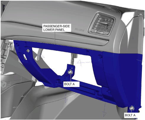
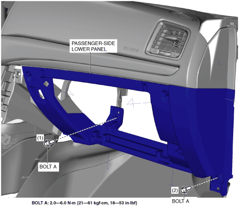
3. Remove bolts A.
am6zzw00011412
|
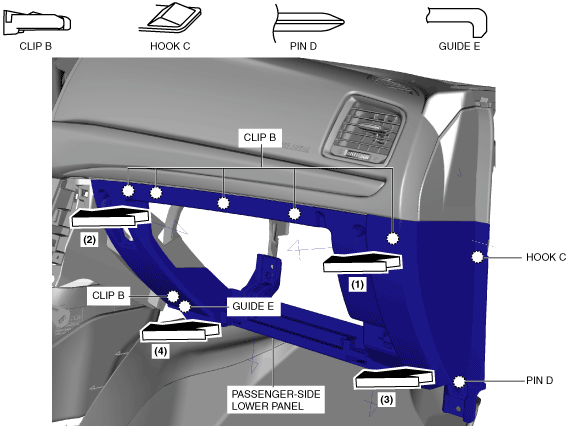
4. Pull the passenger-side lower panel in the direction of the arrow in the order of (1), (2), (3), (4) and remove it while detaching clips B, hook C, pin D and guide E.
am6zzw00012036
|
Installation
1. Install clips B, hook C, pin D and guide E while pressing the shaded area shown in the figure for the passenger-side lower panel in the direction of the arrow in the order of (1), (2), (3), (4) and (5).
am6zzw00012037
|
2. Install bolts A.
am6zzw00011412
|
3. Install the following parts:
4. Connect the negative battery cable. (See NEGATIVE BATTERY CABLE DISCONNECTION/CONNECTION [SKYACTIV-G 2.0, SKYACTIV-G 2.5].) (See NEGATIVE BATTERY CABLE DISCONNECTION/CONNECTION [SKYACTIV-G 2.0, SKYACTIV-G 2.5 (WITHOUT i-stop)].) (See NEGATIVE BATTERY CABLE DISCONNECTION/CONNECTION [SKYACTIV-D 2.2].)
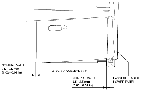
5. After installing the passenger-side lower panel and glove compartment, measure the clearance, and verify that the measurement value is within the specification shown in the figure.
am6zzw00010473
|
Passenger-side lower panel adjustment
1. Remove the grove compartment. (See GLOVE COMPARTMENT REMOVAL/INSTALLATION.)
2. Loosen bolts A.
ac5uuw00001005
|
3. Remove bolts A.
4. Install bolts A in the order of (1), (2) shown in the figure.
ac5uuw00001006
|
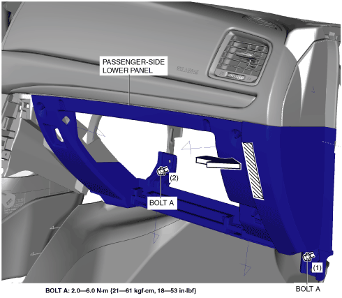
5. Install bolts A in the order of (1) and (2) while pressing the shaded area shown in the figure for the passenger-side lower panel.
ac5uuw00001007
|
6. Install the glove compartment, measure the clearance between the glove compartment and passenger-side lower panel again, and verify that it is within the specification.
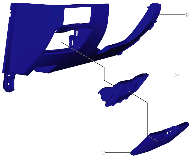
Disassembly/Assembly (Driver-side only)
1. Disassemble in the order indicated in the table.
am6zzw00010841
|
|
1
|
Pocket lid
|
|
2
|
Coin box
|
|
3
|
Lower panel
|
2. Assemble in the reverse order of disassembly.