 |
am6zzw00009237
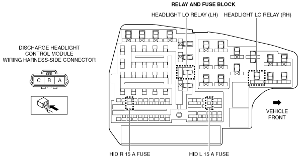
DISCHARGE HEADLIGHT SYSTEM INSPECTION
id091800805400
Terminal layout
am6zzw00009237
|
Inspection procedure
|
Step |
Inspection |
Action |
|
|---|---|---|---|
|
1
|
INSPECT RELAY
• Disconnect the negative battery cable.
• Remove the following relays:
(See RELAY LOCATION.)
• Inspect the relays.
(See RELAY INSPECTION.)
• Are all relays normal?
|
Yes
|
Install the relays, then go to the next step.
(See RELAY LOCATION.)
|
|
No
|
Replace the malfunctioning relay.
(See RELAY LOCATION.)
|
||
|
2
|
INSPECT LIGHT SWITCH
• Inspect the light switch.
(See LIGHT SWITCH INSPECTION.)
• Is the light switch normal?
|
Yes
|
Go to the next step.
|
|
No
|
Replace the light switch.
|
||
|
3
|
INSPECT DISCHARGE HEADLIGHT CONTROL MODULE CONNECTOR
• Disconnect the discharge headlight control module connector.
• Inspect the connector engagement and connection condition and inspect the terminals for damage, deformation, corrosion, or disconnection.
• Is the connector normal?
|
Yes
|
Go to the next step.
|
|
No
|
Repair or replace the connector.
|
||
|
4
|
INSPECT FOR OPEN CIRCUIT IN DISCHARGE HEADLIGHT CONTROL MODULE GROUND CIRCUIT
• Verify that the discharge headlight control module is disconnected.
• Inspect for continuity between discharge headlight control module terminal C (wiring harness-side) and body ground.
• Is there continuity?
|
Yes
|
Go to the next step.
|
|
No
|
Refer to the wiring diagram and verify whether or not there is a common connector between discharge headlight control module terminal C and body ground.
If there is a common connector:
• Determine the malfunctioning part by inspecting the common connector and the terminal for corrosion, damage, or pin disconnection, and the common wiring harness for an open circuit.
• Repair or replace the malfunctioning part.
If there is no common connector:
• Repair or replace the wiring harness which has an open circuit.
|
||
|
5
|
INSPECT DISCHARGE HEADLIGHT CONTROL MODULE POWER SUPPLY CIRCUIT
• Verify that the discharge headlight control module connector is disconnected.
• Reconnect the negative battery cable.
• Turn the light switch to the HEAD position.
• Measure the voltage at discharge headlight control module terminal B (wiring harness-side).
• Is the voltage B+?
|
Yes
|
Turn the light switch to the OFF position, then go to the next step.
|
|
No
|
Inspect the HID L 15 A fuse and HID R 15 A fuse.
• If the fuse is burnt out:
• If the fuse is damaged:
• If the fuse is normal:
|
||
|
6
|
VERIFY IF MALFUNCTION CAUSE IS HEADLIGHT HI/LO BULB OR DISCHARGE HEADLIGHT CONTROL MODULE
• Disconnect the negative battery cable.
• Install a normal headlight HI/LO bulb.
• Make sure to reconnect all disconnected connectors.
• Reconnect the negative battery cable.
• Turn the light switch to the HEAD position.
• Do the headlights LO illuminate?
|
Yes
|
Replace the headlight HI/LO bulb.
|
|
No
|
Replace the discharge headlight control module.
|
||