 |
am6zzw00009721
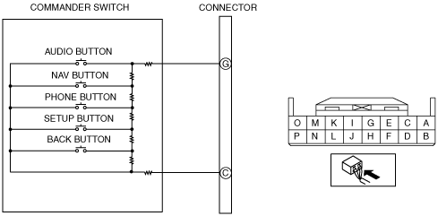
COMMANDER SWITCH INSPECTION
id092000811400
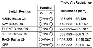
Switch panel
1. Disconnect the negative battery cable. (See NEGATIVE BATTERY CABLE DISCONNECTION/CONNECTION [SKYACTIV-D 2.2].) (See NEGATIVE BATTERY CABLE DISCONNECTION/CONNECTION [SKYACTIV-G 2.0, SKYACTIV-G 2.5].) (See NEGATIVE BATTERY CABLE DISCONNECTION/CONNECTION [SKYACTIV-G 2.0, SKYACTIV-G 2.5 (WITHOUT i-stop)].)
2. Remove the following parts:
3. Verify that the resistance between the commander switch terminals is as indicated in the table.
am6zzw00009721
|
am6zzw00009722
|
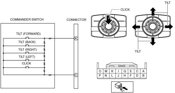
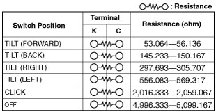
Commander knob (forward, back, left, right)
1. Disconnect the negative battery cable. (See NEGATIVE BATTERY CABLE DISCONNECTION/CONNECTION [SKYACTIV-D 2.2].) (See NEGATIVE BATTERY CABLE DISCONNECTION/CONNECTION [SKYACTIV-G 2.0, SKYACTIV-G 2.5].) (See NEGATIVE BATTERY CABLE DISCONNECTION/CONNECTION [SKYACTIV-G 2.0, SKYACTIV-G 2.5 (WITHOUT i-stop)].)
2. Remove the following parts:
3. Verify that the resistance between the commander switch terminals is as indicated in the table.
am6zzw00011639
|
ac5wzw00003315
|
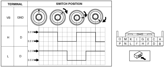
Commander knob (rotation)
1. Connect the commander switch connector.
2. Connect the negative battery cable. (See NEGATIVE BATTERY CABLE DISCONNECTION/CONNECTION [SKYACTIV-D 2.2].) (See NEGATIVE BATTERY CABLE DISCONNECTION/CONNECTION [SKYACTIV-G 2.0, SKYACTIV-G 2.5].) (See NEGATIVE BATTERY CABLE DISCONNECTION/CONNECTION [SKYACTIV-G 2.0, SKYACTIV-G 2.5 (WITHOUT i-stop)].)
3. The ignition is switched to ACC or ON (engine off).
4. When the commander knob is rotated once step at a time, verify that the voltage between terminals and the waveforms are as indicated in the table.
ac5wzw00003316
|