 |
am6zzw00009963
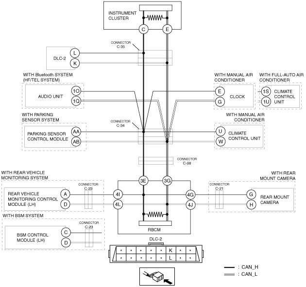
DETERMINING SHORT TO POWER SUPPLY LOCATION (MS-CAN) [SKYACTIV-D 2.2 (R.H.D.)]
id100206001000
System wiring diagram
am6zzw00009963
|
Determination procedure
|
Step |
Inspection |
Action |
|
|---|---|---|---|
|
1
|
INSPECT FOR SHORT TO POWER SUPPLY BETWEEN CONNECTOR C-35 AND INSTRUMENT CLUSTER
• Switch the ignition off (LOCK).
• Disconnect the negative battery cable.
• Disconnect connector C-35.
• Connect the negative battery cable.
• Switch the ignition ON (engine off).
• Measure the voltage at instrument cluster terminals C and E.
• Is the voltage between 1.5 - 3.5 V?
|
Yes
|
Go to Step 3.
|
|
No
|
Go to the next step.
|
||
|
2
|
INSPECT INSTRUMENT CLUSTER FOR SHORT TO POWER SUPPLY
• Switch the ignition off (LOCK).
• Disconnect the negative battery cable.
• Disconnect the instrument cluster connector.
• Connect connector C-35.
• Connect the negative battery cable.
• Switch the ignition ON (engine off).
• Measure the voltage at DLC-2 terminals L and K.
• Is the voltage between 1.5 - 3.5 V?
|
Yes
|
Replace the instrument cluster because there is a short to the power supply in the instrument cluster.
|
|
No
|
Repair or replace the wiring harness between the instrument cluster and connector C-35 because the wiring harness is shorted to the power supply.
|
||
|
3
|
INSPECT FOR SHORT TO POWER SUPPLY BETWEEN CONNECTORS C-35 AND DLC-2
• Measure the voltage at DLC-2 terminals L and K.
• Is the voltage 0 V?
|
Yes
|
Go to the next step.
|
|
No
|
Repair or replace the wiring harness between DLC-2 and connector C-35 because the wiring harness is shorted to the power supply.
|
||
|
4
|
INSPECT FOR SHORT TO POWER SUPPLY BETWEEN CONNECTOR C-34 AND REAR BODY CONTROL MODULE
• Switch the ignition off (LOCK).
• Disconnect the negative battery cable.
• Disconnect the connector C-34.
• Connect the negative battery cable.
• Switch the ignition ON (engine off).
• Measure the voltage at rear body control module (RBCM) terminals 3E and 3G.
• Is the voltage between 1.5 - 3.5 V?
|
Yes
|
Go to the next step.
|
|
No
|
Go to Step 13.
|
||
|
5
|
INSPECT FOR SHORT TO POWER SUPPLY BETWEEN CONNECTOR C-35 AND AUDIO UNIT
• Measure the voltage at audio unit terminals 1O and 1Q.
• Is the voltage between 1.5 - 3.5 V?
|
Yes
|
Go to Step 7.
|
|
No
|
Go to the next step.
|
||
|
6
|
INSPECT AUDIO UNIT FOR SHORT TO POWER SUPPLY
• Switch the ignition off (LOCK).
• Disconnect the negative battery cable.
• Disconnect the audio unit connector.
• Connect connector C-34.
• Connect connector C-35.
• Connect the negative battery cable.
• Switch the ignition ON (engine off).
• Measure the voltage at DLC-2 terminals L and K.
• Is the voltage between 1.5 - 3.5 V?
|
Yes
|
Replace the audio unit because there is a short to the power supply in the audio unit.
|
|
No
|
Repair or replace the wiring harness between the audio unit and connector C-34 because the wiring harness is shorted to the power supply.
|
||
|
7
|
INSPECT FOR SHORT TO POWER SUPPLY BETWEEN CONNECTOR C-35 AND PARKING SENSOR CONTROL MODULE
• Measure the voltage at parking sensor control module terminals AA and AB.
• Is the voltage between 1.5 - 3.5 V?
|
Yes
|
Go to Step 9.
|
|
No
|
Go to the next step.
|
||
|
8
|
INSPECT PARKING SENSOR CONTROL MODULE FOR SHORT TO POWER SUPPLY
• Switch the ignition off (LOCK).
• Disconnect the negative battery cable.
• Disconnect the parking sensor control module connector.
• Connect connector C-35.
• Connect connector C-34.
• Connect the negative battery cable.
• Switch the ignition ON (engine off).
• Measure the voltage at DLC-2 terminals L and K.
• Is the voltage between 1.5 - 3.5 V?
|
Yes
|
Replace the parking sensor control module because there is a short to power supply in the parking sensor control module.
|
|
No
|
Repair or replace the wiring harness between the parking sensor control module and connector C-34 because the wiring harness is shorted to the power supply.
|
||
|
9
|
INSPECT FOR SHORT TO POWER SUPPLY BETWEEN CONNECTOR C-34 AND CLIMATE CONTROL UNIT OR CLOCK
• Measure the voltage at climate control unit terminals 1S and 1U (with full-auto air conditioner).
• Measure the voltage at clock terminals E and G (with manual air conditioner).
• Is the voltage between 1.5 - 3.5 V?
|
Yes
|
Go to Step 11.
|
|
No
|
Go to the next step.
|
||
|
10
|
INSPECT CLIMATE CONTROL UNIT OR CLOCK FOR SHORT TO POWER SUPPLY
• Switch the ignition off (LOCK).
• Disconnect the negative battery cable.
• Disconnect the climate control unit or clock connector.
• Connect connector C-35.
• Connect connector C-34.
• Connect the negative battery cable.
• Switch the ignition ON (engine off).
• Measure the voltage at DLC-2 terminals L and K.
• Is the voltage between 1.5 - 3.5 V?
|
Yes
|
Replace the climate control unit or clock because there is a short to the power supply in the climate control unit or clock.
(See CLOCK REMOVAL/INSTALLATION.)
|
|
No
|
Repair or replace the wiring harness between the climate control unit or clock and connector C-34 because the wiring harness is shorted to the power supply.
|
||
|
11
|
INSPECT FOR SHORT TO POWER SUPPLY BETWEEN CONNECTOR C-34 AND CLIMATE CONTROL UNIT
• Measure the voltage at climate control unit terminals U and W (with manual air conditioner).
• Is the voltage between 1.5 - 3.5 V?
|
Yes
|
Repair or replace the wiring harness between connector C-35 and connector C-34 because the wiring harness is shorted to the power supply.
|
|
No
|
Go to the next step.
|
||
|
12
|
INSPECT CLIMATE CONTROL UNIT FOR SHORT TO POWER SUPPLY
• Switch the ignition off (LOCK).
• Disconnect the negative battery cable.
• Disconnect the climate control unit connector.
• Connect connector C-34.
• Connect connector C-35.
• Connect the negative battery cable.
• Switch the ignition ON (engine off).
• Measure the voltage at DLC-2 terminals L and K.
• Is the voltage between 1.5 - 3.5 V?
|
Yes
|
Replace the climate control unit because there is a short to the power supply in the climate control unit.
|
|
No
|
Repair or replace the wiring harness between the climate control unit and connector C-34 because the wiring harness is shorted to the power supply.
|
||
|
13
|
INSPECT FOR SHORT TO POWER SUPPLY BETWEEN CONNECTOR C-34 AND CONNECTOR C-08
• Switch the ignition off (LOCK).
• Disconnect the negative battery cable.
• Disconnect the connector C-08.
• Connect the connector C-34.
• Connect the connector C-35.
• Connect the negative battery cable.
• Switch the ignition ON (engine off).
• Measure the voltage at DLC-2 terminals L and K.
• Is the voltage between 1.5 - 3.5 V?
|
Yes
|
Go to the next step.
|
|
No
|
Repair or replace the wiring harness between connector C-34 and connector C-08 because the wiring harness is shorted to the power supply.
|
||
|
14
|
INSPECT FOR SHORT TO POWER SUPPLY BETWEEN REAR VEHICLE MONITORING CONTROL MODULE (LH) OR BSM CONTROL MODULE (LH) AND REAR BODY CONTROL MODULE (RBCM)
• Switch the ignition off (LOCK).
• Disconnect the negative battery cable.
• Disconnect the rear body control module (RBCM) connector.
• Connect the negative battery cable.
• Switch the ignition ON (engine off).
• Measure the voltage at rear vehicle monitoring control modules (LH) terminals A and D. (with rear vehicle monitoring system)
• Measure the voltage at BSM control modules (LH) terminals C and D. (with BSM system)
• Is the voltage between 1.5 - 3.5 V?
|
Yes
|
Go to Step 17.
|
|
No
|
Go to the next step.
|
||
|
15
|
INSPECT FOR SHORT TO POWER SUPPLY BETWEEN REAR VEHICLE MONITORING CONTROL MODULE (LH) OR BSM CONTROL MODULE (LH) AND CONNECTOR C-23
• Switch the ignition off (LOCK).
• Disconnect the negative battery cable.
• Disconnect connector C-23.
• Connect the negative battery cable.
• Switch the ignition ON (engine off).
• Measure the voltage at rear vehicle monitoring control modules (LH) terminals A and D. (with rear vehicle monitoring system)
• Measure the voltage at BSM control modules (LH) terminals C and D. (with BSM system)
• Is the voltage between 1.5 - 3.5 V?
|
Yes
|
Repair or replace the wiring harness between the rear body control module (RBCM) or BSM control module (LH) and connector C-23 because the wiring harness is shorted to the power supply.
|
|
No
|
Go to the next step.
|
||
|
16
|
INSPECT REAR VEHICLE MONITORING CONTROL MODULE (LH) OR BSM CONTROL MODULE (LH) FOR SHORT TO POWER SUPPLY
• Switch the ignition off (LOCK).
• Disconnect the negative battery cable.
• Disconnect the rear vehicle monitoring control modules (LH) connector or BSM control modules (LH) connector.
• Connect connector C-23.
• Connect the rear body control module (RBCM) connector.
• Connect connector C-08.
• Connect connector C-34.
• Connect connector C-35.
• Connect the negative battery cable.
• Switch the ignition ON (engine off).
• Measure the voltage at DLC-2 terminals L and K.
• Is the voltage between 1.5 - 3.5 V?
|
Yes
|
Replace the rear vehicle monitoring control modules (LH) or BSM control module (LH) and connector because there is a short to power supply in the rear vehicle monitoring control modules (LH) or BSM control module (LH) and connector.
|
|
No
|
Repair or replace the wiring harness between the rear vehicle monitoring control modules (LH) or BSM control module (LH) and connector C-23 because the wiring harness is shorted to the power supply.
|
||
|
17
|
INSPECT FOR SHORT TO POWER SUPPLY BETWEEN REAR MOUNT CAMERA AND REAR BODY CONTROL MODULE (RBCM)
• Measure the voltage at rear mount camera terminals G and H.
• Is the voltage between 1.5 - 3.5 V?
|
Yes
|
Go to Step 20.
|
|
No
|
Go to the next step.
|
||
|
18
|
INSPECT FOR SHORT TO POWER SUPPLY BETWEEN REAR MOUNT CAMERA AND CONNECTOR C-21
• Switch the ignition off (LOCK).
• Disconnect the negative battery cable.
• Disconnect connector C-21.
• Connect the rear body control module (RBCM) connector.
• Connect connector C-08.
• Connect connector C-34.
• Connect connector C-35.
• Connect the negative battery cable.
• Switch the ignition ON (engine off).
• Measure the voltage at DLC-2 terminals L and K.
• Is the voltage between 1.5 - 3.5 V?
|
Yes
|
Go to the next step.
|
|
No
|
Repair or replace the wiring harness between the rear body control module (RBCM) and connector C-21 because the wiring harness is shorted to the power supply.
|
||
|
19
|
INSPECT REAR MOUNT CAMERA FOR SHORT TO POWER SUPPLY
• Switch the ignition off (LOCK).
• Disconnect the negative battery cable.
• Disconnect the rear mount camera connector.
• Connect connector C-21.
• Connect the negative battery cable.
• Switch the ignition ON (engine off).
• Measure the voltage at DLC-2 terminals L and K.
• Is the voltage between 1.5 - 3.5 V?
|
Yes
|
Replace the rear mount camera because there is a short to power supply in the rear mount camera.
|
|
No
|
Repair or replace the wiring harness between the rear mount camera and connector C-21 because the wiring harness is shorted to the power supply.
|
||
|
20
|
INSPECT REAR BODY CONTROL MODULE (RBCM) FOR SHORT TO POWER SUPPLY
• Switch the ignition off (LOCK).
• Disconnect the negative battery cable.
• Connect connector C-08.
• Connect connector C-34.
• Connect connector C-35.
• Connect the negative battery cable.
• Switch the ignition ON (engine off).
• Measure the voltage at DLC-2 terminals L and K.
• Is the voltage between 1.5 - 3.5 V?
|
Yes
|
Replace the rear body control module (RBCM) because there is a short to the power supply in the rear body control module (RBCM).
|
|
No
|
Repair or replace the wiring harness between the rear body control module (RBCM) and connector C-08 because the wiring harness is shorted to the power supply.
|
||