 |
am6xuw00007828
DISC PAD (REAR) REPLACEMENT
id041100800300
With Double-sided Adhesive Tape
1. Switch to the maintenance mode. (See MAINTENANCE MODE.)
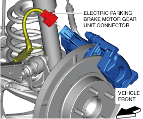
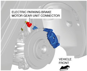
2. Disconnect the electric parking brake motor gear unit connector.
am6xuw00007828
|
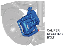
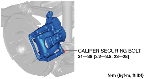
3. Loosen the caliper securing bolt.
am6zzw00014108
|
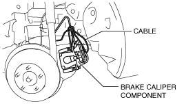
4. Remove the brake caliper component from the hub support and suspend it out of the way with a cable. (See REAR BRAKE (DISC) REMOVAL/INSTALLATION.)
am6xuw00008536
|
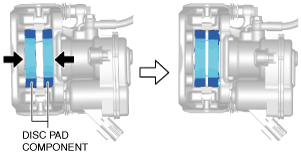
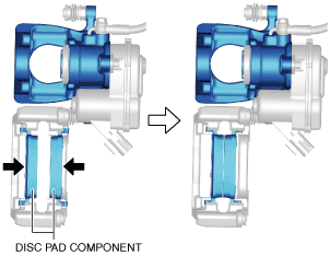
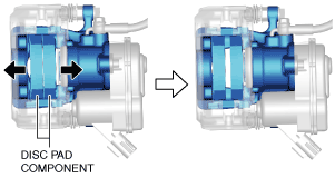
5. Move the disc pad components in the direction of the arrows shown in the figure, then peel off the disc pad components from the caliper and piston.
am6zzw00014109
|
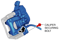
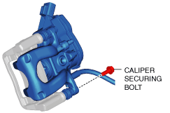
6. Remove the caliper securing bolt.
am6zzw00014110
|
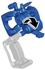
7. Move the caliper in the direction of the arrow shown in the figure.
8. Remove the disc pad components from the mounting support.
9. Clean the double-sided adhesive tape application area from the caliper, piston and disc pad components.
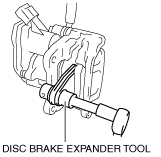
10. Press in the piston using a commercially available disc brake expander tool. (See REAR BRAKE (DISC) REMOVAL/INSTALLATION.)
am6xuw00008537
|
11. Install the new disc pad components to the mounting support.
12. Move the disc pad components in the direction of the arrows shown in the figure.
am6zzw00014111
|
13. Peel off the backing of the double-sided adhesive tape from the disc pad components.
14. Move the caliper in the direction of the arrow as shown in the figure.
aatjjw00012215
|
15. Temporarily install the caliper securing bolt.
am6zzw00014112
|
16. Move the disc pad component in the direction of the arrows shown in the figure, and lightly affix the double-sided adhesive tape on the disc pad components to the piston and caliper.
am6zzw00014113
|
17. Install the brake caliper component. (See REAR BRAKE (DISC) REMOVAL/INSTALLATION.)
18. Install the caliper securing bolt.
am6zzw00014114
|
19. Connect the electric parking brake motor gear unit connector.
am6xuw00007828
|
20. End the maintenance mode. (See MAINTENANCE MODE.)
21. Pump the brake pedal a few times to attach the double-sided adhesive tape on the disc pad components to the caliper and piston by applying pressure.
22. Inspect the following items:
Without Double-sided Adhesive Tape
1. Switch to the maintenance mode. (See MAINTENANCE MODE.)
2. Disconnect the negative battery cable. (See NEGATIVE BATTERY CABLE DISCONNECTION/CONNECTION [SKYACTIV-G 2.0, SKYACTIV-G 2.5].) (See NEGATIVE BATTERY CABLE DISCONNECTION/CONNECTION [SKYACTIV-G 2.0, SKYACTIV-G 2.5 (WITHOUT i-stop)].) (See NEGATIVE BATTERY CABLE DISCONNECTION/CONNECTION [SKYACTIV-D 2.2].)
3. Remove the wheel and tire.
4. Disconnect the electric parking brake motor gear unit connector.
am3zzw00019750
|
5. Remove in the order indicated in the table.
6. Install in the reverse order of removal.
7. End the maintenance mode. (See MAINTENANCE MODE.)
8. After installation, pump the brake pedal a few times and inspect the following:
am3zzw00019751
|
|
1
|
Bolt
(See Bolt Removal Note.)
|
|
2
|
Disc pad
|
Bolt Removal Note
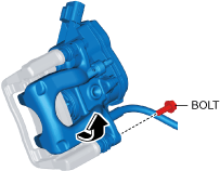
1. Remove the bolt shown in the figure and lift up the caliper.
am3zzw00019752
|
Disc Pad, Bolt Installation Note
1. Clean the exposed area of the piston.
2. Push the piston in using the commercially available disc brake expand tool.
am3zzw00019753
|
3. Install the disc pads to the mounting support.
4. Return the caliper to the original position and install the bolt.
am3zzw00019754
|