 |
ac5wzw00004908
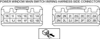
POWER WINDOW MAIN SWITCH INSPECTION
id091200002100
1. Disconnect the negative battery cable. (See NEGATIVE BATTERY CABLE DISCONNECTION/CONNECTION [SKYACTIV-G 2.0, SKYACTIV-G 2.5].) (See NEGATIVE BATTERY CABLE DISCONNECTION/CONNECTION [SKYACTIV-G 2.0, SKYACTIV-G 2.5 (WITHOUT i-stop)].) (See NEGATIVE BATTERY CABLE DISCONNECTION/CONNECTION [SKYACTIV-D 2.2].)
2. Remove the power window main switch (See POWER WINDOW MAIN SWITCH REMOVAL/INSTALLATION.)
3. Connect the power window main switch connector.
4. Connect the negative battery cable. (See NEGATIVE BATTERY CABLE DISCONNECTION/CONNECTION [SKYACTIV-G 2.0, SKYACTIV-G 2.5].) (See NEGATIVE BATTERY CABLE DISCONNECTION/CONNECTION [SKYACTIV-G 2.0, SKYACTIV-G 2.5 (WITHOUT i-stop)].) (See NEGATIVE BATTERY CABLE DISCONNECTION/CONNECTION [SKYACTIV-D 2.2].)
5. Measure the voltage at each terminal.
Terminal Voltage Table (Reference)
ac5wzw00004908
|
|
Terminal |
Signal name |
Connected to |
Measurement condition |
Voltage (V) |
Inspection item (s) |
|---|---|---|---|---|---|
|
1A
|
Sensor power supply
|
Power window motor (driver’s side)
|
Switch the ignition ON (engine on or off)
|
B+
|
• Power window motor (driver’s side)
• Related wiring harness
|
|
Switch the ignition ACC or OFF
|
1.0 or less
|
||||
|
1B
|
Power supply
|
P.WINDOW3 30A fuse
|
Under any condition
|
B+
|
• P.WINDOW3 30A fuse
• Related wiring harness
|
|
1D
|
Driver’s side window open signal
|
Power window motor (driver’s side)
|
Door glass (driver’s side) opening
|
B+
|
• Power window motor (driver’s side)
• Related wiring harness
|
|
while door glass (driver-side) is opening for approx. 40 s after ignition is switched OFF (LOCK) from ON
|
B+
|
||||
|
Other
|
1.0 or less
|
||||
|
1E
|
Door open/close signal
|
Rear body control module (RBCM)
|
Terminal used for communication therefore determination based on terminal voltage is not possible.
|
||
|
1F
|
Driver’s side window close signal
|
Power window motor (driver’s side)
|
Door glass (driver’s side) closing
|
B+
|
• Power window motor (driver’s side)
• Related wiring harness
|
|
while door glass (driver-side) is closing for approx. 40 s after ignition is switched OFF (LOCK) from ON
|
B+
|
||||
|
Other
|
1.0 or less
|
||||
|
1G
|
IG1
|
C/U IG1 15A fuse
|
Switch the ignition ON (engine on or off)
|
B+
|
• C/U IG1 15A fuse
• Related wiring harness
|
|
Switch the ignition OFF (LOCK)
|
1.0 or less
|
||||
|
1I
|
Sensor ground
|
Power window motor (driver’s side)
|
Under any condition
|
1.0 or less
|
• Power window motor (driver’s side)
• Related wiring harness
|
|
1K
|
GND
|
Body ground
|
Under any condition
|
1.0 or less
|
• Related wiring harness
|
|
1L
|
Serial communication
|
Power window subswitch
|
Because this terminal is for communication, good/no good judgment by terminal voltage is not possible
|
• Power window subswitch
• Related wiring harness
|
|
|
2A
|
ACC*1
|
MIRROR 7.5 A fuse
|
Switch the ignition to OFF
|
B+
|
• MIRROR 7.5 A fuse
• Related wiring harness
|
|
Other
|
1.0 or less
|
||||
|
Retractable outer mirror control signal*2
|
Retractable outer mirror
|
Inspect the power outer mirror switch.
|
|||
|
2B
|
Power outer mirror control signal
|
Power outer mirror
|
Inspect the power outer mirror switch.
|
||
|
2C
|
Power outer mirror control signal
|
Power outer mirror
|
Inspect the power outer mirror switch.
|
||
|
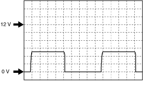
2D
|
Pulse 1
|
Power window motor (driver’s side)
|
Door glass (driver’s side) operating
|
Wave pattern (See Inspection Using an Oscilloscope (Reference).)
|
• Related wiring harness
• Power window motor (driver’s side)
|
|
2E
|
Power outer mirror control signal
|
Power outer mirror
|
Inspect the power outer mirror switch.
|
||
|
2F
|
Pulse 2
|
Power window motor (driver’s side)
|
Door glass (driver’s side) operating
|
Wave pattern (See Inspection Using an Oscilloscope (Reference).)
|
• Power window motor (driver’s side)
• Related wiring harness
|
|
2G
|
Power outer mirror control signal
|
Power outer mirror
|
Inspect the power outer mirror switch.
|
||
|
2H
|
Power outer mirror control signal
|
Power outer mirror
|
Inspect the power outer mirror switch.
|
||
|
2I
|
Power outer mirror control signal
|
Power outer mirror
|
Inspect the power outer mirror switch.
|
||
|
2J
|
Door lock signal
|
Rear body control module (RBCM)
|
Door lock switch ON
|
1.0 or less
|
• Rear body control module (RBCM)
• Related wiring harness
|
|
Other
|
approx. 5.0
|
||||
|
2N
|
GND
|
Body ground
|
Under any condition
|
1.0 or less
|
• Related wiring harness
|
Inspection Using an Oscilloscope (Reference)
am6zzw00009468
|