|
1
|
VERIFY FREEZE FRAME DATA HAS BEEN RECORDED
• Has FREEZE FRAME DATA been recorded?
|
Yes
|
Go to the next step.
|
|
No
|
Record the FREEZE FRAME DATA on the repair order, then go to the next step.
|
|
2
|
VERIFY RELATED SERVICE INFORMATION
• Verify related Service Information availability.
• Is any related Service Information available?
|
Yes
|
Perform repair or diagnosis according to available Service Information.
• If vehicle is not repaired, go to the next step.
|
|
No
|
Go to the next step.
|
|
3
|
VERIFY CURRENT SIGNAL STATUS: IS CONCERN INTERMITTENT OR CONSTANT?
• Connect the M-MDS to the DLC-2.
• Clear the DTC from the PCM memory using the M-MDS.
• Start the engine.
• Is the same DTC present?
|
Yes
|
Go to the next step.
|
|
No
|
Intermittent concern exists.
Perform the “INTERMITTENT CONCERN TROUBLESHOOTING”.
|
|
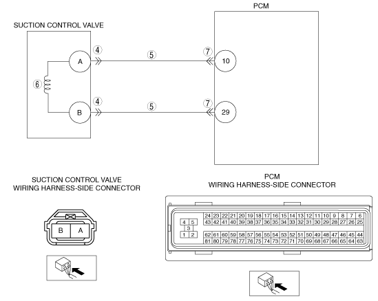
4
|
INSPECT SUCTION CONTROL VALVE CONNECTOR FOR POOR CONNECTION
• Switch the ignition to off.
• Inspect for poor connection (such as damaged/pulled-out terminals, corrosion).
• Is there any malfunction?
|
Yes
|
Repair or replace the suspected terminal, go to Step 8.
|
|
No
|
Go to the next step.
|
|
5
|
INSPECT SUCTION CONTROL VALVE CIRCUIT FOR SHORT TO POWER SUPPLY
• Switch the ignition to ON (Engine off).
• Inspected the voltage between the following terminals and body ground:
-
― Suction control valve terminal A and body ground.
― Suction control valve terminal B and body ground.
• Is the voltage less than 1.0 V?
|
Yes
|
Go to the next step.
|
|
No
|
Repair or replace the wiring harness for a short to power supply, go to Step 8.
|
|
6
|
INSPECT SUCTION CONTROL VALVE
• Inspect the suction control valve.
• Is there any malfunction?
|
Yes
|
Replace the supply pump, go to Step 8.
|
|
No
|
Go to the next step.
|
|
7
|
INSPECT PCM CONNECTOR FOR POOR CONNECTION
• Switch the ignition to off.
• Inspect for poor connection (such as damaged/pulled-out terminals, corrosion).
• Is there any malfunction?
|
Yes
|
Repair or replace the suspected terminal, go to Step 8.
|
|
No
|
Go to the next step.
|
|
8
|
VERIFY TROUBLESHOOTING OF DTC P0629:00 COMPLETED
• Make sure to reconnect all disconnected connectors.
• Start the engine.
• Is the same DTC present?
|
Yes
|
Replace the PCM, go to the next step.
|
|
No
|
Go to the next step.
|
|
9
|
VERIFY AFTER REPAIR PROCEDURE
• Perform the Repair Verification Drive Mode.
• Are any DTCs present?
|
Yes
|
Go to the applicable DTC inspection.
|
|
No
|
Troubleshooting completed.
|