DTC P2148:00 [MZR-CD (RF Turbo)]
id0102f1152900
DTC P2148:00 |
Fuel injector supply circuit high input |
---|---|
DETECTION CONDITION
|
• The PCM monitors the fuel injector circuit voltage while the ignition switch is on. If the PCM detects the circuit voltage is more then threshold when the fuel injector does not inject the fuel, the PCM determines that there is a malfunction in the fuel injector circuit.
Diagnostic support note
• The MIL illuminates if the PCM detects the above malfunction condition in first drive cycle.
• PENDING CODE is available if the PCM detects the above malfunction condition during the first drive cycle.
• FREEZE FRAME DATA is available.
• The DTC is stored in the PCM memory.
|
POSSIBLE CAUSE
|
• Fuel injector malfunction
• Connector or terminal malfunction
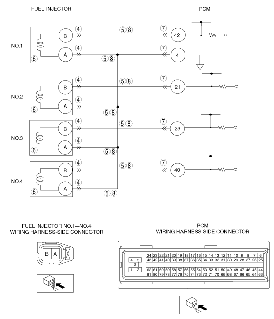
• Open circuit in the wiring harness between the fuel injector No.1 terminal B and PCM terminal 42
• Open circuit in the wiring harness between the fuel injector No.2 terminal B and PCM terminal 21
• Open circuit in the wiring harness between the fuel injector No.3 terminal B and PCM terminal 23
• Open circuit in the wiring harness between the fuel injector No.4 terminal B and PCM terminal 40
• Open in the wiring harness between the fuel injector No.1 terminal A and PCM terminal 4
• Open in the wiring harness between the fuel injector No.2 terminal A and PCM terminal 4
• Open in the wiring harness between the fuel injector No.3 terminal A and PCM terminal 4
• Open in the wiring harness between the fuel injector No.4 terminal A and PCM terminal 4
• Short to power circuit in the wiring harness between the fuel injector No.1 terminal B and PCM terminal 42
• Short to power circuit in the wiring harness between the fuel injector No.2 terminal B and PCM terminal 21
• Short to power circuit in the wiring harness between the fuel injector No.3 terminal B and PCM terminal 23
• Short to power circuit in the wiring harness between the fuel injector No.4 terminal B and PCM terminal 40
• Short to power in the wiring harness between the fuel injector No.1 terminal A and PCM terminal 4
• Short to power in the wiring harness between the fuel injector No.2 terminal A and PCM terminal 4
• Short to power in the wiring harness between the fuel injector No.3 terminal A and PCM terminal 4
• Short to power in the wiring harness between the fuel injector No.4 terminal A and PCM terminal 4
• PCM malfunction
|
![]() |
Diagnostic procedure
STEP |
INSPECTION |
ACTION |
|
---|---|---|---|
1
|
VERIFY FREEZE FRAME DATA HAS BEEN RECORDED
• Has FREEZE FRAME DATA been recorded?
|
Yes
|
Go to the next step.
|
No
|
Record the FREEZE FRAME DATA on the repair order, then go to the next step.
|
||
2
|
VERIFY RELATED SERVICE INFORMATION
• Verify related Service Information availability.
• Is any related Service Information available?
|
Yes
|
Perform repair or diagnosis according to available Service Information.
• If vehicle is not repaired, go to the next step.
|
No
|
Go to the next step.
|
||
3
|
VERIFY CURRENT SIGNAL STATUS: IS CONCERN INTERMITTENT OR CONSTANT?
• Connect the M-MDS to the DLC-2.
• Clear the DTC from the PCM memory using the M-MDS.
• Start the engine.
• Is the PENDING CODE for this DTC present?
|
Yes
|
Go to the next step.
|
No
|
Intermittent concern exists.
Perform the “INTERMITTENT CONCERN TROUBLESHOOTING”.
|
||
4
|
INSPECT FUEL INJECTOR CONNECTOR FOR POOR CONNECTION
• Switch the ignition to off.
• Inspect for poor connection fuel injector for each cylinder (such as damaged/pulled-out terminals, corrosion).
• Is there any malfunction?
|
Yes
|
Repair or replace the suspected terminal, then go to Step 9.
|
No
|
Go to the next step.
|
||
5
|
INSPECT FUEL INJECTORS CIRCUIT FOR SHORT TO POWER SUPPLY
• Switch the ignition to ON (Engine off).
• Disconnect the PCM connector.
• Inspect the voltage between following terminals (wiring harness-side) and body ground:
• Is the voltage B+?
|
Yes
|
Repair or replace the wiring harness for a short to power supply for the suspected cylinder, then go to Step 9.
|
No
|
Go to the next step.
|
||
6
|
INSPECT FUEL INJECTOR
• Inspect the fuel injector.
• Is there any malfunction?
|
Yes
|
Replace the fuel injector, then go to Step 9.
|
No
|
Go to the next step.
|
||
7
|
INSPECT PCM CONNECTOR FOR POOR CONNECTION
• Switch the ignition to off.
• Inspect for poor connection. (such as damaged/pulled-out terminals, corrosion).
• Is there any malfunction?
|
Yes
|
Repair or replace the suspected terminal, then go to Step 9.
|
No
|
Go to the next step.
|
||
8
|
INSPECT FUEL INJECTOR FOR OPEN CIRCUIT
• Switch the ignition to off.
• Inspect for continuity between following terminals (wiring harness-side harness):
• Is there continuity?
|
Yes
|
Go to the next step.
|
No
|
Repair or replace the wiring harness for the suspected circuit, then go to the next step.
|
||
9
|
VERIFY TROUBLESHOOTING OF DTC P2148:00 COMPLETED
• Make sure to reconnect all disconnected connectors.
• Clear the DTC using the M-MDS.
• Start the engine.
• Is the PENDING CODE for this DTC present?
|
Yes
|
Replace the PCM, then go to the next step.
|
No
|
Go to the next step.
|
||
10
|
VERIFY AFTER REPAIR PROCEDURE
• Perform the Repair Verification Drive Mode.
• Are any DTCs present?
|
Yes
|
Go to the applicable DTC troubleshooting.
|
No
|
Troubleshooting completed.
|