|
1
|
VERIFY FREEZE FRAME DATA HAS BEEN RECORDED
• Has FREEZE FRAME DATA been recorded?
|
Yes
|
Go to the next step.
|
|
No
|
Record the FREEZE FRAME DATA on the repair order, then go to the next step.
|
|
2
|
VERIFY RELATED SERVICE INFORMATION
• Verify related Service Information availability.
• Is any related Service Information available?
|
Yes
|
Perform repair or diagnosis according to available Service Information.
• If vehicle is not repaired, go to the next step.
|
|
No
|
Go to the next step.
|
|
3
|
VERIFY CURRENT SIGNAL STATUS: IS CONCERN INTERMITTENT OR CONSTANT?
• Connect the M-MDS to the DLC-2.
• Clear the DTC from the PCM memory using the M-MDS.
• Start the engine.
• Is the same DTC present?
|
Yes
|
Go to the next step.
|
|
No
|
Intermittent concern exists.
Perform the “INTERMITTENT CONCERN TROUBLESHOOTING”.
|
|
4
|
INSPECT BATTERY POSITIVE TERMINAL FOR POOR INSTALLATION
• Switch the ignition to off.
• Inspect battery positive terminal for looseness.
• Is there any malfunction?
|
Yes
|
Connect battery positive terminal correctly, then go to Step 12.
|
|
No
|
Go to the next step.
|
|
5
|
INSPECT GENERATOR TERMINAL FOR POOR INSTALLATION
• Switch the ignition to off.
• Inspect generator terminal B for looseness.
• Is there any malfunction?
|
Yes
|
Connect generator terminal B correctly, then go to Step 12.
|
|
No
|
Go to the next step.
|
|
6
|
INSPECT DRIVE BELT CONDITION
• Verify that drive belt auto tensioner indicator mark does not exceed limit.
• Is drive belt normal?
|
Yes
|
Go to the next step.
|
|
No
|
Replace and/or adjust drive belt, then go to Step 12.
|
|
7
|
INSPECT BATTERY
• Is there any malfunction?
|
Yes
|
Replace the battery, then go to Step 12.
|
|
No
|
Go to the next step.
|
|
8
|
INSPECT GENERATOR
• Is there any malfunction?
|
Yes
|
Replace the generator, then go to Step 12.
|
|
No
|
Go to the next step.
|
|
9
|
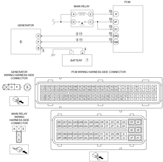
INSPECT GENERATOR CIRCUIT FOR SHORT TO GROUND
• Inspect for continuity between the following terminal:
-
― Generator terminal D (wiring harness-side) and PCM terminal 1BD
― Generator terminal P (wiring harness-side) and PCM terminal 1BK
• Are there continuity?
|
Yes
|
Go to the next step
|
|
No
|
Repair or replace the wiring harness for short, then go to Step 12.
|
|
10
|
INSPECT PCM CONNECTOR FOR POOR CONNECTION
• Switch the ignition to off.
• Disconnect the PCM connector.
• Inspect for poor connection (such as damaged/pulled-out pins, corrosion).
• Are there any malfunction?
|
Yes
|
Repair or replace suspected part, then go to Step 12.
|
|
No
|
Go to the next Step.
|
|
11
|
INSPECT GENERATOR CIRCUIT FOR OPEN CIRCUIT
• Inspect for continuity between the following terminal:
-
― Generator terminal D (wiring harness-side) and PCM terminal 1BD
― Generator terminal P (wiring harness-side) and PCM terminal 1BK
• Are there continuity?
|
Yes
|
Go to the next step.
|
|
No
|
Repair or replace the wiring harness for open, then go to the next step.
|
|
12
|
VERIFY TROUBLESHOOTING OF DTC P0562:00 COMPLETED
• Make sure to reconnect all disconnected connectors.
• Clear the DTC from the PCM memory using the M-MDS.
• Start the engine.
• Is the PENDING CODE for this DTC present?
|
Yes
|
Replace the PCM, then go to the next step.
|
|
No
|
Go to the next step.
|
|
13
|
VERIFY AFTER REPAIR PROCEDURE
• Perform the “AFTER REPAIR PROCEDURE”.
• Are any DTCs present?
|
Yes
|
Go to the applicable DTC inspection.
|
|
No
|
DTC troubleshooting completed.
|