TIMING BELT REMOVAL/INSTALLATION [MZR-CD (RF Turbo)]


id0110f1804000

1.  Disconnect the negative battery cable.

2.  Remove the front tire (RH).

3.  Set the front mudguard (RH) out of the way. (See FRONT MUDGUARD REMOVAL/INSTALLATION.)

4.  Remove the aerodynamic under cover No.2. (See AERODYNAMIC UNDER COVER NO.2 REMOVAL/INSTALLATION.)

5.  Remove the splash shield (RH).

6.  Set the coolant reserve tank out of the way. (See COOLANT RESERVE TANK REMOVAL/INSTALLATION [MZR-CD (RF Turbo)].)

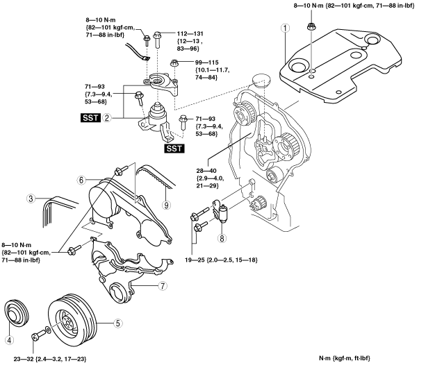
7.  Remove in the order shown in the table.

8.  Install in the reverse order of removal.

9.  Start the engine and inspect the pulleys and the drive belt for runout and contact.

am6zzw00003110

1
Engine cover
2
No.3 engine mount
3
Drive belt
4
Crankshaft pulley cover
5
Crankshaft pulley
6
Upper timing belt cover
7
Lower timing belt cover
8
Timing belt auto tensioner
9
Timing belt


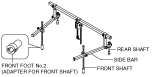
No.3 Engine Mount Removal Note

1.  Air cleaner assembly. (See INTAKE-AIR SYSTEM REMOVAL/INSTALLATION [MZR-CD (RF Turbo)].)

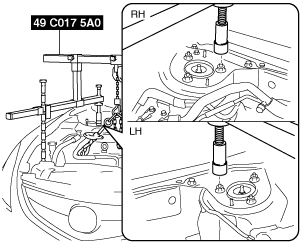
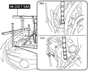
2.  Install the SST using the following procedure.

Caution
•  Refer to the SST instruction manual for the basic handing procedure.
am6zzw00000924
(1)  As shown in the figure, set the rear shafts of the SST to the left and right shock absorber bolts.
am6zzw00000925
(2)  Install front foot No.2 to the left/right front shaft of the SST, then align the groove of the front shaft of the SST with the folded up part of the vehicle as shown in the figure.
am6zzw00000926
(3)  Adjust the positions of the SST side bars so that they are the same height (left and right) and horizontal.
(4)  Make sure each joint is securely tightened.

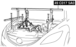
3.  Support the engine using the SST.

am6zzw00000927


Timing Belt, Timing Belt Auto Tensioner Removal Note

Caution
•  After removing the timing belt, do not move the crankshaft and/or camshaft from this position because it can cause the valve and piston to come into contact.
•  Forcefully twisting the belt, turning it inside out, or allowing oil or grease on it will damage the belt and shorten its life.
Note
•  Mark the timing belt rotation on the belt for proper reinstallation.
am6zzw00003618

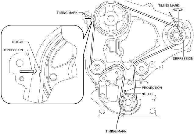
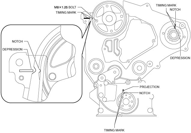
1.  Turn the crankshaft clockwise and align the timing marks as shown.

am5ezw00006554

2.  Remove the timing belt auto tensioner.


Timing Belt, Timing Belt Auto Tensioner Installation Note

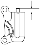
1.  Measure the tensioned rod projection length.

•  If not as specified, replace the timing belt auto tensioner.
am3zzw00004166
Projection (free length)
12.9—14.6 mm {0.508—0.574 in}

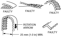
2.  Inspect the timing belt auto tensioner for oil leakage.

•  If not as specified, replace the timing belt auto tensioner.

Caution
•  Placing the timing belt auto tensioner horizontally can cause oil leakage and damage the timing belt auto tensioner. Place the timing belt auto tensioner vertically when using a vise.

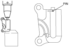
3.  Verify the thrust of the timing belt auto tensioner rod in the following order:

•  If the timing belt auto tensioner rod is rigid when it is pushed with a force of approximately 235 N {24 kgf, 53 Ibf}, push it down slowly and fix the pin in the hole.
•  If there is no resistance on the timing belt auto tensioner rod and it moves slightly when it is pushed with a force of approximately 235 N {24 kgf, 53 Ibf};
(1)  Push it down slowly two or three times to the bottom end of the rod.
(2)  If the rod protrudes approximately 8.1 mm {0.32 in}, verify that there is resistance on the timing belt auto tensioner rod.
Caution
•  To prevent damage to the inside of the timing belt auto tensioner, do not press down the timing belt auto tensioner rod with a force greater than the specified 235 N {24 kgf, 53 lbf}.
Be careful that the rod does not touch the bottom.
•  If the timing belt auto tensioner rod projection is restored, push it down slowly and fix the pin in the hole.
―  If the resistance is not restored, replace the timing belt auto tensioner.
am3zzw00004167
Caution
•  To prevent the bolts from damaging the fuel injection pump and pulley, do not fully tighten the fixing bolts. If it contacts the pulley surface, it will damage the pulley.

4.  Verify that all timing marks are correctly aligned.

•  If not, align all timing marks according to the procedure below.

5.  Fix the camshaft pulley to the cylinder head using bolt (M8 x1.25).

am5ezw00006555

Caution
•  Turn the crankshaft in the direction which will prevent the TDC and BDC from being passed. Otherwise it can cause the valve and piston to come into contact.
(1)  Turn the crankshaft and set it at an angle of 45° or more away from the TDC and BDC.
(2)  Align the timing marks of the camshaft pulley.
(3)  Align the timing marks of the supply pump pulley.
(4)  Turn the crankshaft and align the timing marks of the timing belt pulley.

6.  Install the timing belt on the pulleys in the order shown below.

(1)  Timing belt pulley
(2)  Idler
(3)  Supply pump pulley
(4)  Camshaft pulley
(5)  Water pump pulley
(6)  Tensioner pulley
am3zzw00004298

7.  Remove the camshaft pulley fixing bolt.

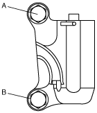
8.  Hand tighten the timing belt auto tensioner bolts in the order A to B as indicated in the figure.

9.  Tighten the timing belt auto tensioner bolts in the order A to B as indicated in the figure.

am3zzw00004168

Tightening torque
19—25 N·m {2.0—2.5 kgf·m, 15—18 ft·lbf}

10.  Remove the pin from the timing belt auto tensioner to apply tension to the belt.

11.  Turn the crankshaft clockwise twice, and align the timing marks.

12.  Verify that all timing marks are correctly aligned.

•  If not as specified, repeat from Timing Belt Auto Tensioner Removal Note. (See Timing Belt, Timing Belt Auto Tensioner Removal Note.)


Crankshaft Pulley Installation Note

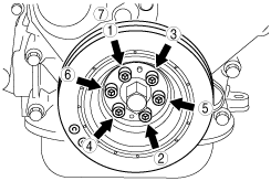
1.  Tighten the bolts in the order shown.

am3zzw00003968

Tightening torque
23—32 N·m {2.4—3.2 kgf·m, 17—23 ft·lbf}


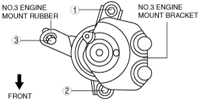
No.3 Engine Mount Installation Note

Note
•  If the No.3 engine mount bracket and the engine are removed, retighten the No.3 engine mount stud bolts.

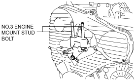
1.  Tighten the No.3 engine mount stud bolts.

am6zzw00003689

Tightening torque
28—40 N·m {2.9—4.0 kgf·m, 21—29 ft·lbf}

2.  Install the No.3 engine mount rubber hand-tighten.

3.  Temporarily the No.3 engine mount rubber bolts in the order as shown.

am6zzw00003128

4.  Tighten the No.3 engine mount rubber bolts.

Tightening torque
71—93 N·m {7.3—9.4 kgf·m, 53—68 ft·lbf}

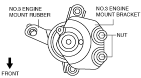
5.  Temporarily the No.3 engine mount bracket nuts in the figure.

am6zzw00003147

6.  Tighten the No.3 engine mount bracket bolt and nuts in the order as shown.

am6zzw00003139

Tightening torque
1: 112—131 N·m {12—13 kgf·m, 83—96 ft·lbf}
2: 99—115 N·m {10.1—11.7 kgf·m, 74—84 ft·lbf}