 |
am6zzw00008018
INTAKE-AIR SYSTEM REMOVAL/INSTALLATION [L8, LF, L5]
id0113a0800400
1. Complete the “BEFORE SERVICE PRECAUTION”. (See BEFORE SERVICE PRECAUTION [L8, LF, L5].)
2. Disconnect the negative battery cable. (See BATTERY REMOVAL/INSTALLATION [L8, LF, L5].)
3. Remove in the order indicated in the table.
4. Install in the reverse order of removal.
5. Complete the “AFTER SERVICE PRECAUTION”. (See AFTER SERVICE PRECAUTION [L8, LF, L5].)
6. Add the engine coolant to the cooling system filler neck and the coolant reserve tank to replace that during servicing.
7. Inspect the engine coolant level. (See ENGINE COOLANT LEVEL INSPECTION [L8, LF, L5].)
8. Inspect for engine coolant leakage. (See ENGINE COOLANT LEAKAGE INSPECTION [L8, LF, L5].)
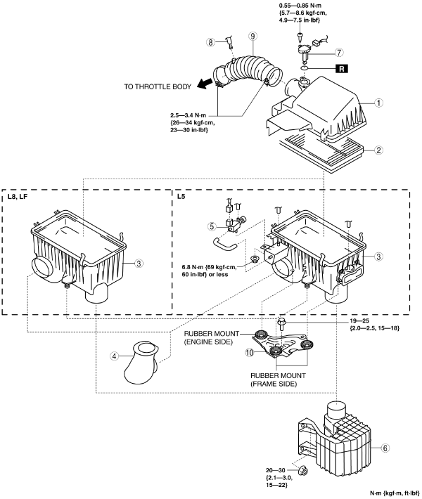
Step 1
am6zzw00008018
|
|
1
|
Air cleaner cover
|
|
2
|
Air cleaner element
|
|
3
|
Air cleaner case
|
|
4
|
Fresh-air duct
|
|
5
|
VAD solenoid valve (L5)
|
|
6
|
Resonance chamber
|
|
7
|
MAF/IAT sensor
|
|
8
|
Ventilation hose (air cleaner side)
|
|
9
|
Air hose
(See Air Hose Removal Note.)
|
|
10
|
Air cleaner bracket
|
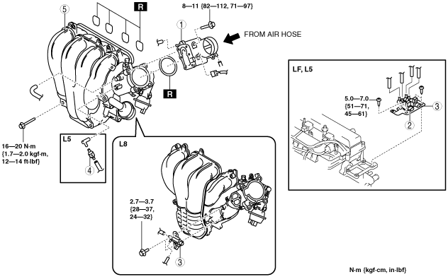
Step 2
am6zzw00008019
|
|
1
|
Throttle Body
(See Throttle Body Removal Note.)
|
|
2
|
Variable intake air solenoid valve (LF, L5)
|
|
3
|
Variable tumble solenoid valve
|
|
4
|
VAD check valve (L5)
|
|
5
|
Intake manifold
(See Intake Manifold Removal Note.)
|
Resonance Chamber Removal Note
1. Remove the front mudguard (LH). (See FRONT MUDGUARD REMOVAL/INSTALLATION.)
2. Remove the resonance chamber.
Air Hose Removal Note
1. Remove the purge solenoid valve bracket. (See PURGE SOLENOID VALVE REMOVAL/INSTALLATION [L8, LF, L5].)
2. Remove the air hose.
Throttle Body Removal Note
1. Wrap a clean cloth around the cooling system cap and release the pressure by loosening the cap slowly.
2. Remove the water hose from the throttle body and plug the water hose quickly.
3. Remove the throttle body.
Intake Manifold Removal Note
1. Remove the aerodynamic under cover No.2. (See AERODYNAMIC UNDER COVER NO.2 REMOVAL/INSTALLATION.)
2. Remove the coolant reserve tank. (See COOLANT RESERVE TANK REMOVAL/INSTALLATION [L8, LF, L5].)
3. Remove all clips for securing wiring harnesses from the intake manifold.
4. Disconnect the vacuum hoses connecting the intake manifold.
5. Remove the fuel distributor. (See FUEL INJECTOR REMOVAL/INSTALLATION [L8, LF, L5].)
6. Remove the intake manifold.
Throttle Body Installation Note
1. Tighten the installation bolts in the order shown in the figure.
am6zzw00008020
|
2. Remove the plug from the water hose and install the water hose to the throttle body quickly.
Air Cleaner Case Installation Note
1. Verify that the rubber mounts are set in the air cleaner bracket (3 locations).
2. Install the projections on the frame side (2 locations).
3. Verify that the projections on the frame side are installed securely.
4. Install the projection on the engine side (remaining location).
5. Verify that the projection on the engine side installed securely.
Ventilation Hose (Air Hose Side) Installation Note
1. Connect the ventilation hose (air hose side).
2. Verify that the ventilation hose connection area is inserted completely.