 |
am6zzw00001642
TIRE PRESSURE MONITORING SYSTEM (TPMS) ON-BOARD DIAGNOSIS
id020200800200
On-Board Diagnostic (OBD) Test Description
Read/clear diagnostic results
PID/Data monitor and record
Reading DTCs Procedure
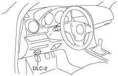
1. Connect the M-MDS to the DLC-2.
am6zzw00001642
|
2. After the vehicle is identified, select the following items from the initialization screen of the M-MDS.
3. Verify the DTC according to the directions on the screen.
4. After completion of repairs, clear all DTCs stored in the instrument cluster. (See DTC TABLE [INSTRUMENT CLUSTER].)
Clearing DTCs Procedures
1. Connect the M-MDS to the DLC-2.
am6zzw00001642
|
2. After the vehicle is identified, select the following items from the initialization screen of the M-MDS.
3. Verify the DTC according to the directions on the screen.
4. Press the clear button on the DTC screen to clear the DTC.
5. Switch the ignition to off.
6. Switch the ignition to ON and wait for 5 s or more.
7. Perform DTC inspection. (See DTC Table.)
8. Verify that no DTCs are displayed.
PID/Data Monitor and Record Procedure
1. Connect the M-MDS to the DLC-2.
am6zzw00001642
|
2. After the vehicle is identified, select the following items from the initialization screen of the M-MDS.
3. Select the applicable PID from the PID table.
4. Verify the PID data according to the directions on the screen.
DTC Table
|
DTC |
Description |
Page |
|---|---|---|
|
M-MDS |
||
|
C0077:00
|
Low tire pressure
|
(See DTC C0077:00.)
|
|
C2011:49
|
Wheel unit No.1 internal malfunction
|
|
|
C2012:49
|
Wheel unit No.2 internal malfunction
|
|
|
C2013:49
|
Wheel unit No.3 internal malfunction
|
|
|
C2014:49
|
Wheel unit No.4 internal malfunction
|
|
|
C2011:87
|
Wheel unit No.1 (No response)
|
|
|
C2012:87
|
Wheel unit No.2 (No response)
|
|
|
C2013:87
|
Wheel unit No.3 (No response)
|
|
|
C2014:87
|
Wheel unit No.4 (No response)
|
|
|
U0100:00
|
PCM communication error
|
|
|
U0127:00
|
Communication failure between instrument cluster and keyless receiver
|
(See DTC U0127:00.)
|
|
U0300:00
|
Instrument cluster internal configuration data error
|
(See DTC U0300:00.)
|
|
U0401:68
|
Signal error from PCM
|
|
|
U2100:00
|
Instrument cluster configuration not implemented
|
|
|
U3000:42
|
Instrument cluster general memory failure
|
(See DTC U3000:42.)
|
PID/DATA Monitor Table
|
PID Name (Definition) |
Unit/ Condition |
Condition/Specification |
Action |
|---|---|---|---|
|
WU1_ID
WU2_ID
WU3_ID
WU4_ID
(Wheel unit ID code)
|
–
|
Indicates the registered ID that is transmitted from the wheel unit.
|
• Replace the wheel unit.
• Perform the wheel unit ID registration.
|
|
WU1_P
WU2_P
WU3_P
WU4_P
(Tire pressure)
|
Pa, psi
|
Indicates the tire pressure. (See WHEEL AND TIRE SPECIFICATION [European (L.H.D. U.K.) Specs.].)
|
• Adjust tire pressure.
• Replace the wheel unit.
• Perform the wheel unit ID registration.
|
|
WU1_T
WU2_T
WU3_T
WU4_T
(Tire temperature)
|
°C, °F
|
Indicates the internal tire air temperature.
|
Adjust tire pressure.
|
|
WU1_VPWR
WU2_VPWR
WU3_VPWR
WU4_VPWR
(Supply voltage)
|
Normal/Error
|
Signal is normal: Normal
Signal is abnormal: Error
|
Replace the wheel unit.
|
|
WU1_ERR_T
WU2_ERR_T
WU3_ERR_T
WU4_ERR_T
(Tire temperature)
|
Normal/Error
|
Signal is normal: Normal
Signal is abnormal: Error
|
Replace the wheel unit.
|
|
WU1_ERR_P
WU2_ERR_P
WU3_ERR_P
WU4_ERR_P
(Tire pressure)
|
Normal/Error
|
Signal is normal: Normal
Signal is abnormal: Error
|
Replace the wheel unit.
|