DTC U0127:00
id020200801300
With Advanced Keyless Entry And Push Button Start System
DTC U0127:00 |
• Communication failure between instrument cluster and keyless receiver
|
---|---|
DETECTION CONDITION
|
• The instrument cluster cannot receive signal from the keyless CM.
|
POSSIBLE CAUSE
|
• Open or short circuit in the wiring harness between the keyless CM terminal 2F and the instrument cluster terminal 2N.
• Keyless control module malfunction.
• Instrument cluster malfunction.
• Poor connection at connectors (female terminal)
• BCM malfunction
|
![]() |
Diagnostic procedure
STEP |
INSPECTION |
ACTION |
|
---|---|---|---|
1
|
INSPECT WHEEL UNIT SIGNAL FOR OPEN CIRCUIT
• Switch the ignition to off.
• Disconnect keyless CM, instrument cluster and BCM connectors.
• Inspect for continuity between keyless CM terminal 2F (harness-side) and instrument cluster terminal 2N (harness-side).
• Inspect for continuity between keyless CM terminal 2F (harness-side) and BCM terminal 6J (harness-side).
• Is there continuity?
|
Yes
|
Go to the next step.
|
No
|
Repair or replace the following wiring harness for an open circuit, then go to Step 5.
― Between keyless CM terminal 2F and instrument cluster terminal 2N
― Between keyless CM terminal 2F and BCM terminal 6J
|
||
2
|
INSPECT WHEEL UNIT SIGNAL FOR SHORT TO POWER
• Switch the ignition to off.
• Disconnect keyless CM, instrument cluster and BCM connectors.
• Measure the voltage between keyless CM terminal 2F (harness-side) and ground.
• Is there B+?
|
Yes
|
Repair or replace the following wiring harness for a short to power, then go to Step 5.
― Between keyless CM terminal 2F and instrument cluster terminal 2N
― Between keyless CM terminal 2F and BCM terminal 6J
|
No
|
Go to the next step.
|
||
3
|
INSPECT WHEEL UNIT SIGNAL FOR SHORT TO GROUND
• Switch the ignition to off.
• Disconnect keyless CM, instrument cluster and BCM connectors.
• Inspect for continuity between keyless CM terminal 2F (harness-side) and ground.
• Is there continuity?
|
Yes
|
Repair or replace the following wiring harness for a short to ground, then go to Step 5.
― Between keyless CM terminal 2F and instrument cluster terminal 2N
― Between keyless CM terminal 2F and BCM terminal 6J
|
No
|
Go to the next step.
|
||
4
|
INSPECT FOR KEYLESS CM MALFUNCTION
• Switch the ignition to off.
• Using the M-MDS, perform the DTC inspection for the keyless CM.
• Is any DTCs present?
|
Yes
|
Go to the applicable DTC inspection. (See DTC TABLE [ADVANCED KEYLESS ENTRY AND PUSH BUTTON START SYSTEM].)
|
No
|
Go to the next step.
|
||
5
|
INSPECT FOR BCM MALFUNCTION
• Switch the ignition to off.
• Using the M-MDS, perform the DTC inspection for the BCM.
• Is any DTCs present?
|
Yes
|
Go to the applicable DTC inspection. (See DTC TABLE [BCM].)
|
No
|
Go to the next step.
|
||
6
|
VERIFY TROUBLESHOOTING COMPLETED
• Clear the DTC from the memory.
• Switch the ignition to ON and wait for 30 s.
• Is the same DTC present?
|
Yes
|
• If the malfunction recurs, replace the instrument cluster. (See INSTRUMENT CLUSTER REMOVAL/INSTALLATION.)
• Configure the instrument cluster. (See INSTRUMENT CLUSTER CONFIGURATION.)
• Register the wheel unit ID. (See WHEEL UNIT ID REGISTRATION.)
• Go to the next step.
|
No
|
Go to the next step.
|
||
7
|
VERIFY AFTER REPAIR PROCEDURE
• Drive the vehicle at a speed of 25 km/h {15.5 mph} or more for 10 min or more.
• Are there any other DTCs present?
|
Yes
|
Go to the applicable DTC inspection. (See TIRE PRESSURE MONITORING SYSTEM (TPMS) ON-BOARD DIAGNOSIS.)
|
No
|
DTC troubleshooting completed.
|
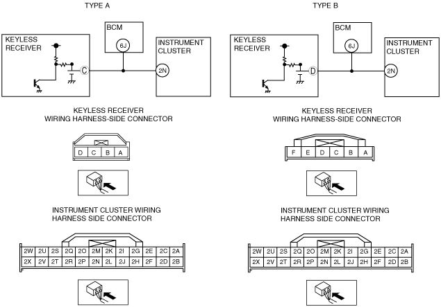
Without Advanced Keyless Entry And Push Button Start System
DTC U0127:00 |
• Communication failure between instrument cluster and keyless receiver
|
---|---|
DETECTION CONDITION
|
• The instrument cluster cannot receive signal from the keyless receiver.
|
POSSIBLE CAUSE
|
Type A
• Open or short circuit in the wiring harness between the keyless receiver terminal C and the instrument cluster terminal 2N.
• Keyless receiver malfunction.
• Instrument cluster malfunction.
• Poor connection at connectors (female terminal)
• BCM malfunction
Type B
• Open or short circuit in the wiring harness between the keyless receiver terminal D and the instrument cluster terminal 2N.
• Keyless receiver malfunction.
• Instrument cluster malfunction.
• Poor connection at connectors (female terminal)
• BCM malfunction
|
![]() |
Diagnostic procedure
Type A
STEP |
INSPECTION |
ACTION |
|
---|---|---|---|
1
|
INSPECT WHEEL UNIT SIGNAL FOR OPEN CIRCUIT
• Switch the ignition to off.
• Disconnect keyless receiver, instrument cluster and BCM connectors.
• Inspect for continuity between keyless receiver terminal C (harness-side) and instrument cluster terminal 2N (harness-side).
• Is there continuity?
|
Yes
|
Go to the next step.
|
No
|
Repair or replace the following wiring harness for an open circuit, then go to Step 4.
― Between keyless receiver terminal C and instrument cluster terminal 2N
― Between keyless receiver terminal C and BCM terminal 6J
|
||
2
|
INSPECT WHEEL UNIT SIGNAL FOR SHORT TO POWER
• Switch the ignition to off.
• Disconnect keyless receiver, instrument cluster and BCM connectors.
• Measure the voltage between keyless receiver terminal C (harness-side) and ground.
• Is there B+?
|
Yes
|
Repair or replace the following wiring harness for a short to power, then go to Step 4.
― Between keyless receiver terminal C and instrument cluster terminal 2N
― Between keyless receiver terminal C and BCM terminal 6J
|
No
|
Go to the next step.
|
||
3
|
INSPECT WHEEL UNIT SIGNAL FOR SHORT TO GROUND
• Switch the ignition to off.
• Disconnect keyless receiver, instrument cluster and BCM connectors.
• Inspect for continuity between keyless receiver terminal C (harness-side) and ground.
• Is there continuity?
|
Yes
|
Repair or replace the following wiring harness for a short to ground, then go to the next step.
― Between keyless receiver terminal C and instrument cluster terminal 2N
― Between keyless receiver terminal C and BCM terminal 6J
|
No
|
Replace keyless receiver, then go to the next step. (See KEYLESS RECEIVER REMOVAL/INSTALLATION [KEYLESS ENTRY SYSTEM].) (See KEYLESS RECEIVER REMOVAL/INSTALLATION [ADVANCED KEYLESS ENTRY AND PUSH BUTTON START SYSTEM].)
|
||
4
|
INSPECT FOR BCM MALFUNCTION
• Switch the ignition to off.
• Using the M-MDS, perform the DTC inspection for the BCM.
• Is any DTCs present?
|
Yes
|
Go to the applicable DTC inspection. (See DTC TABLE [BCM].)
|
No
|
Go to the next step.
|
||
5
|
VERIFY TROUBLESHOOTING COMPLETED
• Clear the DTC from the memory.
• Switch the ignition to ON and wait for 30 s.
• Is the same DTC present?
|
Yes
|
• If the malfunction recurs, replace the instrument cluster. (See INSTRUMENT CLUSTER REMOVAL/INSTALLATION.)
• Configure the instrument cluster. (See INSTRUMENT CLUSTER CONFIGURATION.)
• Register the wheel unit ID. (See WHEEL UNIT ID REGISTRATION.)
• Go to the next step.
|
No
|
Go to the next step.
|
||
6
|
VERIFY AFTER REPAIR PROCEDURE
• Drive the vehicle at a speed of 25 km/h {15.5 mph} or more for 10 min or more.
• Are there any other DTCs present?
|
Yes
|
Go to the applicable DTC inspection. (See TIRE PRESSURE MONITORING SYSTEM (TPMS) ON-BOARD DIAGNOSIS.)
|
No
|
DTC troubleshooting completed.
|
Type B
STEP |
INSPECTION |
ACTION |
|
---|---|---|---|
1
|
INSPECT WHEEL UNIT SIGNAL FOR OPEN CIRCUIT
• Switch the ignition to off.
• Disconnect keyless receiver, instrument cluster and BCM connectors.
• Inspect for continuity between keyless receiver terminal D (harness-side) and instrument cluster terminal 2N (harness-side).
• Is there continuity?
|
Yes
|
Go to the next step.
|
No
|
Repair or replace the following wiring harness for an open circuit, then go to Step 4.
― Between keyless receiver terminal D and instrument cluster terminal 2N
― Between keyless receiver terminal D and BCM terminal 6J
|
||
2
|
INSPECT WHEEL UNIT SIGNAL FOR SHORT TO POWER
• Switch the ignition to off.
• Disconnect keyless receiver, instrument cluster and BCM connectors.
• Measure the voltage between keyless receiver terminal D (harness-side) and ground.
• Is there B+?
|
Yes
|
Repair or replace the following wiring harness for a short to power, then go to Step 4.
― Between keyless receiver terminal D and instrument cluster terminal 2N
― Between keyless receiver terminal D and BCM terminal 6J
|
No
|
Go to the next step.
|
||
3
|
INSPECT WHEEL UNIT SIGNAL FOR SHORT TO GROUND
• Switch the ignition to off.
• Disconnect keyless receiver, instrument cluster and BCM connectors.
• Inspect for continuity between keyless receiver terminal D (harness-side) and ground.
• Is there continuity?
|
Yes
|
Repair or replace the following wiring harness for a short to ground, then go to the next step.
― Between keyless receiver terminal D and instrument cluster terminal 2N
― Between keyless receiver terminal D and BCM terminal 6J
|
No
|
Replace keyless receiver, then go to the next step. (See KEYLESS RECEIVER REMOVAL/INSTALLATION [KEYLESS ENTRY SYSTEM].) (See KEYLESS RECEIVER REMOVAL/INSTALLATION [ADVANCED KEYLESS ENTRY AND PUSH BUTTON START SYSTEM].)
|
||
4
|
INSPECT FOR BCM MALFUNCTION
• Switch the ignition to off.
• Using the M-MDS, perform the DTC inspection for the BCM.
• Is any DTCs present?
|
Yes
|
Go to the applicable DTC inspection. (See DTC TABLE [BCM].)
|
No
|
Go to the next step.
|
||
5
|
VERIFY TROUBLESHOOTING COMPLETED
• Clear the DTC from the memory.
• Switch the ignition to ON and wait for 30 s.
• Is the same DTC present?
|
Yes
|
• If the malfunction recurs, replace the instrument cluster. (See INSTRUMENT CLUSTER REMOVAL/INSTALLATION.)
• Configure the instrument cluster. (See INSTRUMENT CLUSTER CONFIGURATION.)
• Register the wheel unit ID. (See WHEEL UNIT ID REGISTRATION.)
• Go to the next step.
|
No
|
Go to the next step.
|
||
6
|
VERIFY AFTER REPAIR PROCEDURE
• Drive the vehicle at a speed of 25 km/h {15.5 mph} or more for 10 min or more.
• Are there any other DTCs present?
|
Yes
|
Go to the applicable DTC inspection. (See TIRE PRESSURE MONITORING SYSTEM (TPMS) ON-BOARD DIAGNOSIS.)
|
No
|
DTC troubleshooting completed.
|