STEP
INSPECTION
ACTION
1
CONFIRM INSTRUMENT CLUSTER DTC
• Retrieve the instrument cluster DTC using the M-MDS.
• Is DTC U0415:92 retrieved?
Yes
Go to the next step.
No
Go to Step 11.
2
CONFIRM ABS HU/CM DTC
• Retrieve the ABS HU/CM DTC using the M-MDS.
(See ON-BOARD DIAGNOSIS [ABS].)
• Is any DTC retrieved?
Yes
Perform the applicable DTC troubleshooting procedure.
No
If communication error message is displayed on M-MDS screen, go to the next step.
If communication error message is not displayed, go to Step 7.
3
INSPECT FOR CONNECTION OF ABS HU/CM CONNECTOR
• Is the ABS connector connected securely?
Yes
Go to the next step.
No
Connect the connector securely, then go to Step 7.
4
INSPECT ABS POWER SUPPLY FUSE
• Is ABS power supply fuse normal?
Yes
Go to the next step.
No
Inspect for a short to ground on blown fuse’s circuit.
Repair or replace as necessary.
Install appropriate amperage fuse.
*5
VERIFY WHETHER MALFUNCTION IS IN WIRING HARNESS (BETWEEN ABS HU/CM POWER SUPPLY AND ABS HU/CM FOR CONTINUITY) OR ELSEWHERE
• Switch the ignition to ON.
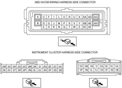
• Measure the voltage at ABS HU/CM terminal AF.
• Is voltage approx. 12 V?
Yes
Go to the next step.
No
Inspect for open circuit between ABS HU/CM and ignition.
Repair or replace as necessary.
*6
VERIFY WHETHER MALFUNCTION IS IN WIRING HARNESS (BETWEEN INSTRUMENT CLUSTER AND GND FOR CONTINUITY) OR ABS HU/CM
• Switch the ignition to off.
• Disconnect the instrument cluster.
• Verify continuity between the harness-side connector terminal A and GND.
• Is there continuity?
Yes
Replace the ABS HU/CM. (Internal malfunction.)
No
Repair or replace malfunctioning part for open circuit and poor contact in GND point.
7
VERIFY WHETHER MALFUNCTION IS IN ABS HU/CM IGNITION POWER SUPPLY SYSTEM (TERMINAL AF) OR ELSEWHERE
• Switch the ignition to ON.
• Monitor ABS HU/CM PID VPWR using the M-MDS.
(See ON-BOARD DIAGNOSIS [ABS].)
• Is the monitored value above 10 V?
Yes
Go to Step 11.
No
Go to the next step.
8
INSPECT BATTERY
• Is the battery voltage normal?
Yes
Go to the next step.
No
Charge or replace the battery, then go to the next step.
9
INSPECT CHARGING SYSTEM WITH ELECTRICAL LOAD OPERATING
• Is battery voltage normal with electrical load (A/C, headlight, rear window defroster, etc.) on the engine idling?
Yes
Go to the next step.
No
Inspect the charging system (drive belt tension, generator, etc.).
*10
VERIFY WHETHER MALFUNCTION IS IN WIRING HARNESS (BETWEEN ABS HU/CM POWER SUPPLY AND ABS HU/CM FOR CONTINUITY) OR ELSEWHERE
• Switch the ignition to ON.
• Measure the voltage at ABS HU/CM terminal AF.
• Is voltage above 10 V?
Yes
Replace the ABS HU/CM. (Internal fault.)
No
Inspect for open circuit between ABS HU/CM and ignition.
Repair or replace as necessary.
11
VERIFY WHETHER MALFUNCTION IS IN INSTRUMENT CLUSTER OR ABS HU/CM
• Turn on and off all warning lights and indicator lights using the instrument cluster PID WL+IL of active command modes using the M-MDS.
• Does the ABS warning light and brake warning light turn on and off according to simulation status?
Yes
Replace the ABS HU/CM. (Internal fault.)
No
Replace the instrument cluster.