 |
am6zzw00001521
DSC HU/CM REMOVAL/INSTALLATION
id041500801000
1. Remove in the order indicated in the table.
2. Install in the reverse order of removal.
3. Add brake fluid, bleed the brakes, and inspect for leakage after the installation has been completed. (See AIR BLEEDING.)
4. Configurate the DSC HU/CM (only when replacing it). (See DSC CONFIGURATION.)
5. Clear the DTCs from the memory. (See ON-BOARD DIAGNOSIS [DYNAMIC STABILITY CONTROL (DSC)].)
am6zzw00001521
|
|
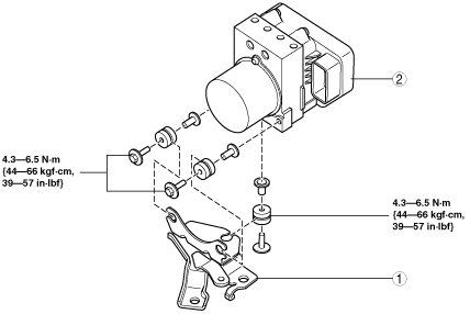
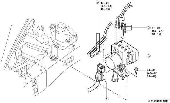
1
|
Connector
(See Connector Removal Note.)
(See Connector Installation Note.)
|
|
2
|
Brake pipe
(See Brake Pipe Removal Note.)
(See Brake Pipe Installation Note.)
|
|
3
|
DSC HU/CM component
|
am6zzw00001522
|
|
1
|
Bracket
|
|
2
|
DSC HU/CM
|
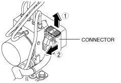
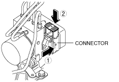
Connector Removal Note
1. Disconnect the connector in the order shown in the figure.
am6zzw00001523
|
Brake Pipe Removal Note
1. Place an alignment mark on the brake pipe and DSC HU/CM.
am6zzw00001524
|
2. Affix protective tape to the connector to prevent brake fluid from entering.
3. Remove the brake pipe.
4. Adhere protective tape to the installation area of the DSC HU/CM brake pipe to prevent foreign material penetration.
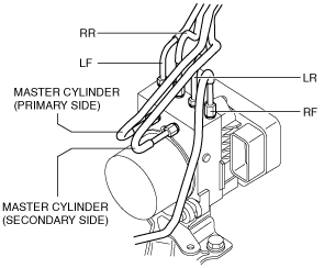
Brake Pipe Installation Note
1. Align the marks made before removal and install the brake pipe into the DSC HU/CM referring to the figure.
am6zzw00001525
|
Connector Installation Note
1. Connect the connector in the order shown in the figure.
am6zzw00001526
|
2. After connecting the connector, verify that the connector is completely locked.