|
1
|
INSPECT WIPER 20 A FUSE
• Switch the ignition to off.
• Disconnect the negative battery cable.
• Remove the WIPER 20 A fuse.
• Inspect the fuse.
• Is the WIPER 20 A fuse normal?
|
Yes
|
Go to the next step.
|
|
No
|
Replace the WIPER 20 A fuse.
After replacement, go to Step 7.
|
|
2
|
INSPECT RELAY BLOCK CONNECTOR CONDITION
• Disconnect the relay block connector.
• Inspect the connector and terminals (corrosion, damage, pin disconnection).
• Is the connector normal?
|
Yes
|
Go to the next step.
|
|
No
|
Repair/replace the connector or terminal.
After repair procedure, go to Step 7.
|
|
3
|
INSPECT RELAY BLOCK
• Inspect the relay block.
• Is the relay block normal?
|
Yes
|
Go to the next step.
|
|
No
|
Replace the relay block.
After replacement, go to Step 7.
|
|
4
|
INSPECT KEYLESS CONTROL MODULE CONNECTOR CONDITION
• Disconnect the keyless control module connector.
• Inspect the connector and terminals (corrosion, damage, pin disconnection).
• Is the connector normal?
|
Yes
|
Go to the next step.
|
|
No
|
Repair/replace the connector or terminal.
After repair procedure, go to Step 7.
|
|
5
|
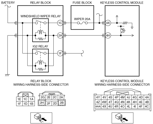
INSPECT IG2 MONITOR INPUT CIRCUIT FOR SHORT CIRCUIT TO GROUND
• Install the WIPER 20 A fuse.
• Inspect for continuity between keyless control module connector terminal 4X and body ground.
• Is there continuity?
|
Yes
|
Repair/replace the wiring harness.
After repair procedure, go to Step 7.
|
|
No
|
Go to the next step.
|
|
6
|
INSPECT IG2 MONITOR INPUT CIRCUIT FOR OPEN CIRCUIT
• Inspect for continuity between relay block connector terminal 1C and keyless control module connector terminal 4X.
• Is there continuity?
|
Yes
|
Go to the next step.
|
|
No
|
Repair/replace the wiring harness.
After repair procedure, go to the next step.
|
|
7
|
VERIFY DTC
• Install the WIPER 20 A fuse.
• Reconnect the disconnected connectors and the negative battery cable.
• Clear DTC using the M-MDS.
• Verify DTC using the M-MDS.
• Is the same DTC present?
|
Yes
|
Repeat the inspection from Step 1.
If the malfunction recurs, replace the keyless control module.
Go to the next step.
|
|
No
|
Go to the next step.
|
|
8
|
VERIFY THAT NO OTHER DTCs ARE PRESENT
• Are there other DTCs output?
|
Yes
|
Perform the corresponding DTC inspection.
|
|
No
|
DTC troubleshooting completed.
|