 |
am6zzw00004798
SECURITY LIGHT: NOT ILLUMINATED, DTC B10E6:12/- [IMMOBILIZER SYSTEM (ADVANCED KEYLESS ENTRY AND PUSH BUTTON START SYSTEM)]
id09021d905600
|
DTC |
Security light flashing pattern |
- |
Voltage higher than the specification (2.2—6.5 V) is detected for 0.05 s while the coil antenna power supply circuit is not active |
|
|---|---|---|---|---|
|
M-MDS display |
Keyless control module |
B10E6:12 |
||
|
PCM |
- |
|||
|
POSSIBLE CAUSE
|
• Connector or terminal malfunction
• Short to power supply in coil antenna power supply circuit
• Push button start malfunction
• Coil antenna malfunction
• Keyless control module malfunction
|
|||
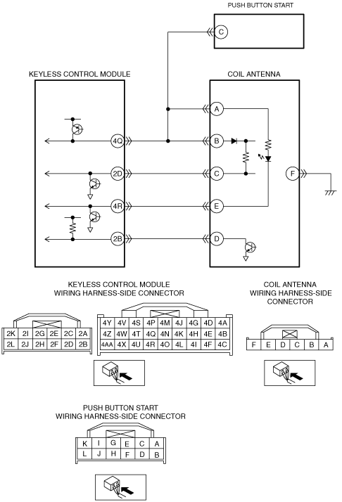
System Wiring Diagram
am6zzw00004798
|
Diagnostic Procedure
|
Step |
Inspection |
Action |
|
|---|---|---|---|
|
1
|
INSPECT COIL ANTENNA CONNECTOR CONDITION
• Switch the ignition to off.
• Disconnect the negative battery cable.
• Disconnect the coil antenna connector.
• Inspect the connector and terminals (corrosion, damage, pin disconnection).
• Is there any malfunction?
|
Yes
|
Repair or replace the connector or terminals, then go to the next step.
|
|
No
|
Go to the next step.
|
||
|
2
|
INSPECT KEYLESS CONTROL MODULE CONNECTOR CONDITION
• Disconnect the keyless control module connector.
• Inspect the connector and terminals (corrosion, damage, pin disconnection).
• Is there any malfunction?
|
Yes
|
Repair or replace the connector or terminals, then go to the next step.
|
|
No
|
Go to the next step.
|
||
|
3
|
INSPECT PUSH BUTTON START CONNECTOR CONDITION
• Disconnect the push button start connector.
• Inspect the connector and terminals (corrosion, damage, pin disconnection).
• Is there any malfunction?
|
Yes
|
Repair or replace the connector or terminals, then go to the next step.
|
|
No
|
Go to the next step.
|
||
|
4
|
INSPECT COIL ANTENNA POWER SUPPLY CIRCUIT FOR SHORT TO POWER SUPPLY
• Reconnect the negative battery cable.
• Measure the voltage between keyless control module terminal 4Q (wiring harness-side) and body ground.
• Is the voltage more than 2.2 V?
|
Yes
|
Repair or replace the wiring harness for a possible short to power supply, then go to the next step.
|
|
No
|
Go to the next step.
|
||
|
5
|
INSPECT PUSH BUTTON START
• Reconnect the push button start connector.
• Measure the voltage between keyless control module terminal 4Q (wiring harness-side) and body ground.
• Is the voltage more than 2.2 V?
|
Yes
|
Replace the push button start, then go to the next step.
|
|
No
|
Go to the next step.
|
||
|
6
|
INSPECT COIL ANTENNA
• Reconnect the coil antenna connector.
• Measure the voltage between keyless control module terminal 4Q (wiring harness-side) and body ground.
• Is the voltage more than 2.2 V?
|
Yes
|
Replace the coil antenna, then go to the next step.
|
|
No
|
Go to the next step.
|
||
|
7
|
PERFORM DTC INSPECTION
• Reconnect the keyless control module connector.
• Clear the DTC from the keyless control module and PCM memory using the M-MDS.
• Disconnect the negative battery cable.
• Reconnect the negative battery cable.
• Perform the immobilizer system (advanced keyless entry and push button start system) DTC inspection using the M-MDS.
• Is the same DTC present?
|
Yes
|
Replace the keyless control module and program the immobilizer system-related parts, then go to the next step.
|
|
No
|
Go to the next step.
|
||
|
8
|
VERIFY THAT NO OTHER DTCs ARE PRESENT
• Are any DTCs present?
|
Yes
|
Go to the applicable DTC inspection.
|
|
No
|
DTC troubleshooting completed.
|
||