 |
am6zzw00002044
DTC B1174:13 [BCM]
id0902f5415300
Malfunction Location
Detection Condition
Possible Causes
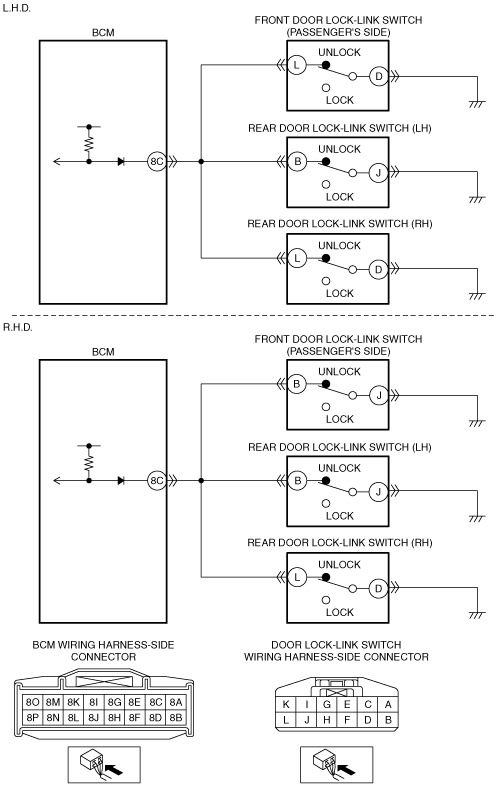
L.H.D.
R.H.D.
System Wiring Diagram
am6zzw00002044
|
Diagnostic Procedure
|
Step |
Inspection |
Action |
|
|---|---|---|---|
|
1
|
PERFORM DTC INSPECTION
• Clear DTCs using the M-MDS.
(See CLEARING DTC [BCM].)
• Perform the BCM DTC inspection using the M-MDS with the door lock-link switch unlocked.
(See DTC INSPECTION [BCM].)
• Is DTC B1174:13 displayed?
|
Yes
|
Go to the next step.
|
|
No
|
DTC troubleshooting completed.
|
||
|
2
|
DETERMINE THE MALFUNCTIONING BASED ON THE MALFUNCTIONING LOCATION
• Operate the door lock-link switch LOCK and UNLOCK.
• Is there a door lock-link switch that does not operate?
|
Yes
|
Only the front door lock-link switch (passenger’s side) does not operate
• Go to Step 5.
Only the rear door lock-link switch (LH) does not operate
• Go to Step 11.
Only the rear door lock-link switch (RH) does not operate
• Go to Step 17.
All door lock-link switches do not operate
• Go to the next step.
|
|
No
|
Go to Step 23.
|
||
|
3
|
INSPECT BCM CONNECTOR CONDITION
• Switch the ignition to off.
• Disconnect the negative battery cable.
• Disconnect the BCM connector.
• Inspect the connector and terminals (corrosion, damage, pin disconnection).
• Is the connector normal?
|
Yes
|
Go to the next step.
|
|
No
|
Repair/replace the connector or terminal.
After repair procedure, go to Step 23.
|
||
|
4
|
INSPECT FRONT DOOR LOCK-LINK SWITCH (PASSENGER’S SIDE), REAR DOOR LOCK-LINK SWITCH (LH), REAR DOOR LOCK-LINK SWITCH (RH) CIRCUIT FOR OPEN CIRCUIT
L.H.D.
• Disconnect the front door lock-link switch (passenger's side) connector.
• Inspect for continuity between front door lock-link switch (passenger's side) connector terminal L and BCM connector terminal 8C.
• Is there continuity?
R.H.D.
• Disconnect the front door lock-link switch (passenger's side) connector.
• Inspect for continuity between front door lock-link switch (passenger's side) connector terminal B and BCM connector terminal 8C.
• Is there continuity?
|
Yes
|
Go to Step 23.
|
|
No
|
Repair/replace the wiring harness.
After repair procedure, go to Step 23.
|
||
|
5
|
INSPECT FRONT DOOR LOCK-LINK SWITCH (PASSENGER’S SIDE) CONNECTOR CONDITION
• Switch the ignition to off.
• Disconnect the negative battery cable.
• Disconnect the front door lock-link switch (passenger's side) connector.
• Inspect the connector and terminals (corrosion, damage, pin disconnection).
• Is the connector normal?
|
Yes
|
Go to the next step.
|
|
No
|
Repair/replace the connector or terminal.
After repair procedure, go to Step 23.
|
||
|
6
|
INSPECT FRONT DOOR LOCK-LINK SWITCH (PASSENGER’S SIDE) CIRCUIT FOR OPEN CIRCUIT
L.H.D.
• Reconnect the negative battery cable.
• Measure the voltage at front door lock-link switch (passenger's side) connector terminal L.
• Can the voltage be measured?
R.H.D.
• Reconnect the negative battery cable.
• Measure the voltage at front door lock-link switch (passenger's side) connector terminal B.
• Can the voltage be measured?
|
Yes
|
Go to the next step.
|
|
No
|
Go to Step 9.
|
||
|
7
|
INSPECT FRONT DOOR LOCK-LINK SWITCH (PASSENGER’S SIDE) CIRCUIT FOR OPEN CIRCUIT
L.H.D.
• Inspect for continuity between front door lock-link switch (passenger's side) connector terminal D and body ground.
• Is there continuity?
R.H.D.
• Inspect for continuity between front door lock-link switch (passenger's side) connector terminal J and body ground.
• Is there continuity?
|
Yes
|
Go to the next step.
|
|
No
|
Repair/replace the wiring harness.
After repair procedure, go to Step 23.
|
||
|
8
|
INSPECT FRONT DOOR LOCK-LINK SWITCH (PASSENGER’S SIDE)
• Inspect the front door lock-link switch (passenger's side).
• Is the front door lock-link switch (passenger's side) normal?
|
Yes
|
Go to Step 23.
|
|
No
|
Replace the front door lock-link switch (passenger's side).
After replacement, go to Step 23.
|
||
|
9
|
INSPECT BCM CONNECTOR CONDITION
• Disconnect the negative battery cable.
• Disconnect the BCM connector.
• Inspect the connector and terminals (corrosion, damage, pin disconnection).
• Is the connector normal?
|
Yes
|
Go to the next step.
|
|
No
|
Repair/replace the connector or terminal.
After repair procedure, go to Step 23.
|
||
|
10
|
INSPECT BCM
• Reconnect the BCM connector.
• Reconnect the negative battery cable.
• Measure the voltage at BCM connector terminal 8C.
• Is the voltage normal?
|
Yes
|
Go to Step 23.
|
|
No
|
Repair/replace the wiring harness.
After repair procedure, go to Step 23.
|
||
|
11
|
INSPECT REAR DOOR LOCK-LINK SWITCH (LH) CONNECTOR CONDITION
• Switch the ignition to off.
• Disconnect the negative battery cable.
• Disconnect the rear door lock-link switch (LH) connector.
• Inspect the connector and terminals (corrosion, damage, pin disconnection).
• Is the connector normal?
|
Yes
|
Go to the next step.
|
|
No
|
Repair/replace the connector or terminal.
After repair procedure, go to Step 23.
|
||
|
12
|
INSPECT REAR DOOR LOCK-LINK SWITCH (LH) CIRCUIT FOR OPEN CIRCUIT
• Reconnect the negative battery cable.
• Measure the voltage at rear door lock-link switch (LH) connector terminal B.
• Can the voltage be measured?
|
Yes
|
Go to the next step.
|
|
No
|
Go to Step 15.
|
||
|
13
|
INSPECT REAR DOOR LOCK-LINK SWITCH (LH) CIRCUIT FOR OPEN CIRCUIT
• Inspect for continuity between rear door lock-link switch (LH) connector terminal J and body ground.
• Is there continuity?
|
Yes
|
Go to the next step.
|
|
No
|
Repair/replace the wiring harness.
After repair procedure, go to Step 23.
|
||
|
14
|
INSPECT REAR DOOR LOCK-LINK SWITCH (LH)
• Inspect the rear door lock-link switch (LH).
• Is the rear door lock-link switch (LH) normal?
|
Yes
|
Go to Step 23.
|
|
No
|
Replace the rear door lock-link switch (LH).
After replacement, go to Step 23.
|
||
|
15
|
INSPECT BCM CONNECTOR CONDITION
• Disconnect the negative battery cable.
• Disconnect the BCM connector.
• Inspect the connector and terminals (corrosion, damage, pin disconnection).
• Is the connector normal?
|
Yes
|
Go to the next step.
|
|
No
|
Repair/replace the connector or terminal.
After repair procedure, go to Step 23.
|
||
|
16
|
INSPECT BCM
• Reconnect the BCM connector.
• Reconnect the negative battery cable.
• Measure the voltage at BCM connector terminal 8C.
• Is the voltage normal?
|
Yes
|
Go to Step 23.
|
|
No
|
Repair/replace the wiring harness.
After repair procedure, go to Step 23.
|
||
|
17
|
INSPECT REAR DOOR LOCK-LINK SWITCH (RH) CONNECTOR CONDITION
• Switch the ignition to off.
• Disconnect the negative battery cable.
• Disconnect the rear door lock-link switch (RH) connector.
• Inspect the connector and terminals (corrosion, damage, pin disconnection).
• Is the connector normal?
|
Yes
|
Go to the next step.
|
|
No
|
Repair/replace the connector or terminal.
After repair procedure, go to Step 23.
|
||
|
18
|
INSPECT REAR DOOR LOCK-LINK SWITCH (RH) CIRCUIT FOR OPEN CIRCUIT
• Reconnect the negative battery cable.
• Measure the voltage at rear door lock-link switch (RH) connector terminal L.
• Can the voltage be measured?
|
Yes
|
Go to the next step.
|
|
No
|
Go to Step 21.
|
||
|
19
|
INSPECT REAR DOOR LOCK-LINK SWITCH (RH) CIRCUIT FOR OPEN CIRCUIT
• Inspect for continuity between rear door lock-link switch (RH) connector terminal D and body ground.
• Is there continuity?
|
Yes
|
Go to the next step.
|
|
No
|
Repair/replace the wiring harness.
After repair procedure, go to Step 23.
|
||
|
20
|
INSPECT REAR DOOR LOCK-LINK SWITCH (RH)
• Inspect the rear door lock-link switch (RH).
• Is the rear door lock-link switch (RH) normal?
|
Yes
|
Go to Step 23.
|
|
No
|
Replace the rear door lock-link switch (RH).
After replacement, go to Step 23.
|
||
|
21
|
INSPECT BCM CONNECTOR CONDITION
• Disconnect the negative battery cable.
• Disconnect the BCM connector.
• Inspect the connector and terminals (corrosion, damage, pin disconnection).
• Is the connector normal?
|
Yes
|
Go to the next step.
|
|
No
|
Repair/replace the connector or terminal.
After repair procedure, go to Step 23.
|
||
|
22
|
INSPECT BCM
• Reconnect the BCM connector.
• Reconnect the negative battery cable.
• Measure the voltage at BCM connector terminal 8C.
• Is the voltage normal?
|
Yes
|
Go to the next step.
|
|
No
|
Repair/replace the wiring harness.
After repair procedure, go to the next step.
|
||
|
23
|
VERIFY DTC
• Reconnect the disconnected connectors and the negative battery cable.
• Clear DTCs using the M-MDS.
(See CLEARING DTC [BCM].)
• Perform the BCM DTC inspection using the M-MDS with the door lock-link switch unlocked.
(See DTC INSPECTION [BCM].)
• Is the same DTC present?
|
Yes
|
Repeat the inspection from Step 1.
If the malfunction recurs, replace the BCM.
Go to the next step.
|
|
No
|
Go to the next step.
|
||
|
24
|
VERIFY THAT NO OTHER DTCs ARE PRESENT
• Are there other DTCs output?
|
Yes
|
Perform the corresponding DTC inspection.
|
|
No
|
DTC troubleshooting completed.
|
||