 |
am6zzw00004456
DTC U3003:16, U3003:17 [REAR VEHICLE MONITORING SYSTEM]
id0902z2884400
Malfunction location
Detection condition
Possible Causes
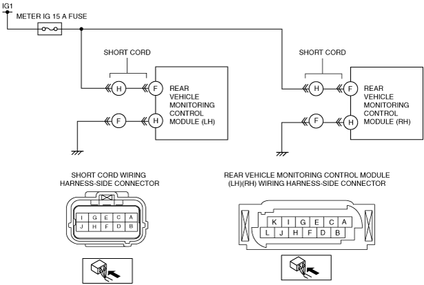
System Wiring Diagram
am6zzw00004456
|
Diagnostic Procedure
|
Step |
Inspection |
Action |
|
|---|---|---|---|
|
1
|
PERFORM DTC INSPECTION
• Clear DTCs using the M-MDS. (See CLEARING DTC [REAR VEHICLE MONITORING SYSTEM].)
• Perform the rear vehicle monitoring control module DTC inspection using the M-MDS. (See DTC INSPECTION [REAR VEHICLE MONITORING SYSTEM].)
• Is DTC U3003:16 or U3003:17 displayed?
|
Yes
|
Go to the next step.
|
|
No
|
DTC troubleshooting completed.
|
||
|
2
|
INSPECT BATTERY VOLTAGE
• Refer to the battery inspection and inspect the battery.
• Is the battery normal?
|
Yes
|
Go to the next step.
|
|
No
|
Replace or charge the battery.
Verify that the repairs have been completed.
|
||
|
3
|
INSPECT FUSE
• Switch the ignition to off (LOCK).
• Disconnect the negative battery cable.
• Remove the METER IG 15 A fuse.
• Are the fuses normal?
|
Yes
|
Install the fuse, then go to the next step.
|
|
No
|
Replace the METER IG 15 A fuse.
Verify that the repairs have been completed.
|
||
|
4
|
INSPECT GENERATOR
• Start the engine.
• Measure the voltage at rear vehicle monitoring control module (RH) connector terminal F.
• Is the voltage between 9—16 V?
|
Yes
|
Inspect the generator.
|
|
No
|
Go to the next step.
|
||
|
5
|
INSPECT REAR VEHICLE MONITORING CONTROL MODULE GND TERMINAL FOR OPEN CIRCUIT
• Measure the voltage at rear vehicle monitoring control module (RH) connector terminal H.
• Is the voltage 0 V?
|
Yes
|
Go to the next step.
|
|
No
|
Repair or replace the malfunctioning wiring harness.
Verify that the repairs have been completed.
|
||
|
6
|
MEASURE REAR VEHICLE MONITORING CONTROL MODULE INPUT VOLTAGE
• Switch the ignition to ON.
• Measure the voltage at rear vehicle monitoring control module (RH) connector terminal F.
• Is the voltage between 9—16 V?
|
Yes
|
Go to the next step.
|
|
No
|
Repair or replace the malfunctioning wiring harness.
Verify that the repairs have been completed.
|
||
|
7
|
VERIFY CORRECTION COMPLETED
• Clear DTCs using the M-MDS or equivalent. (See CLEARING DTC [REAR VEHICLE MONITORING SYSTEM].)
• Perform the rear vehicle monitoring control module DTC inspection using the M-MDS.
• Is DTC U3003:16 or U3003:17 displayed?
|
Yes
|
Replace the rear vehicle monitoring control module (RH).
|
|
No
|
Go to the next step.
|
||
|
8
|
VERIFY THAT NO OTHER DTCs ARE RECORDED
• Are any other DTCs displayed?
|
Yes
|
Perform the corresponding DTC inspection.
|
|
No
|
DTC troubleshooting completed.
|
||