 |
am6zzw00004454
DTC U0028:87 [REAR VEHICLE MONITORING SYSTEM]
id0902z2886700
Malfunction location
Detection condition
Possible Causes
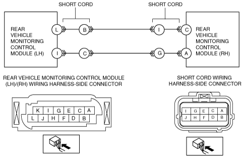
System Wiring Diagram
am6zzw00004454
|
Diagnostic Procedure
|
Step |
Inspection |
Action |
|
|---|---|---|---|
|
1
|
PERFORM DTC INSPECTION
• Clear DTCs using the M-MDS. (See CLEARING DTC [REAR VEHICLE MONITORING SYSTEM].)
• Perform the rear vehicle monitoring control module DTC inspection using the M-MDS. (See DTC INSPECTION [REAR VEHICLE MONITORING SYSTEM].)
• Is DTC U0028:87 displayed?
|
Yes
|
Go to the next step.
|
|
No
|
DTC troubleshooting completed.
|
||
|
2
|
VERIFY REAR VEHICLE MONITORING CONTROL MODULE CONNECTOR CONDITION
• Disconnect the negative battery cable.
• Disconnect the rear vehicle monitoring control modules (RH)/(LH) connectors.
• Verify the connector and terminal condition. (Corrosion, damage, and disconnected pins)
• Are the connectors and terminals normal?
|
Yes
|
Go to the next step.
|
|
No
|
Repair or replace the malfunctioning wiring harness, connector and terminal.
Verify that the repairs have been completed.
|
||
|
3
|
INSPECT CAN BUS CIRCUIT FOR OPEN CIRCUIT
• Inspect the wiring harness for continuity between the following rear vehicle monitoring control module (RH) connector and rear vehicle monitoring control module (LH) connector.
• Is there continuity?
|
Yes
|
Go to the next step.
|
|
No
|
Repair or replace the malfunctioning wiring harness.
Verify that the repairs have been completed.
|
||
|
4
|
INSPECT CAN BUS CIRCUIT FOR SHORT TO GROUND
• Start the engine.
• Inspect the wiring harness for continuity between the following rear vehicle monitoring control module (RH) and body ground.
• Is there continuity?
|
Yes
|
Go to the next step.
|
|
No
|
Repair or replace the malfunctioning wiring harness.
Verify that the repairs have been completed.
|
||
|
5
|
INSPECT CAN BUS CIRCUIT FOR SHORT CIRCUIT
• Inspect the wiring harness for continuity between the following rear vehicle monitoring control module (RH)/(LH) connectors.
• Is there continuity?
|
Yes
|
Go to the next step.
|
|
No
|
Repair or replace the malfunctioning wiring harness.
Verify that the repairs have been completed.
|
||
|
6
|
INSPECT CAN BUS CIRCUIT FOR SHORT TO POWER SUPPLY
• Connect the negative battery cable.
• Switch the ignition to ON.
• Measure the voltage at the following rear vehicle monitoring control module (RH) connector.
• Is the voltage measured?
|
Yes
|
Repair or replace the malfunctioning wiring harness.
Verify that the repairs have been completed.
|
|
No
|
Go to the next step.
|
||
|
7
|
VERIFY DTCs
• Switch the ignition to off (LOCK).
• Disconnect the negative battery cable.
• Reconnect the disconnected connectors.
• Connect the negative battery cable.
• Clear DTCs using the M-MDS.
• Perform the rear vehicle monitoring control module DTC inspection using the M-MDS.
• Is DTC U0028:87 displayed?
|
Yes
|
Replace the rear vehicle monitoring control module (RH), then go to the next step.
|
|
No
|
Go to Step 9.
|
||
|
8
|
VERIFY CORRECTION COMPLETED
• Connect the negative battery cable.
• Clear DTCs using the M-MDS. (See CLEARING DTC [REAR VEHICLE MONITORING SYSTEM].)
• Perform the rear vehicle monitoring control module DTC inspection using the M-MDS.
• Is DTC U0028:87 displayed?
|
Yes
|
Replace the rear vehicle monitoring control module (LH).
|
|
No
|
Go to the next step.
|
||
|
9
|
VERIFY THAT NO OTHER DTCs ARE RECORDED
• Are any other DTCs displayed?
|
Yes
|
Perform the corresponding DTC inspection.
|
|
No
|
DTC troubleshooting completed.
|
||